

Key Takeaways for Vibration-Critical Flip Chip Designs
- Flip-chip solder joints in aerospace and defense electronics face high fatigue risk under random vibration, with stress concentrating at corner bumps and PCB-side intermetallic layers.
- Five linked design variables, bump location, underfill modulus, PCB stiffness, solder alloy and combined thermal-vibration loading, must be tuned together for reliable interconnect life.
- Accurate fatigue-life prediction depends on a modal-to-harmonic-to-fatigue FEA workflow that uses copper-pattern-informed properties and board-level test correlation.
- Device-level qualification data alone cannot predict board-level solder-joint performance. Program-specific vibration profiles and combined-environment testing capture real damage mechanisms.
- Pro-Active Engineering delivers an integrated ITAR-registered workflow that spans DFM, underfill selection, assembly and board-level testing in a single facility, engage the engineering team early in the design phase.
Problem/Solution 1: Corner-Bump Stress and Board Fixation Strategy
The problem: Out-of-plane PCB bending under vibration creates a load path that terminates at the solder bumps. Corner solder joints in board-level packages can experience increased stresses on the PCB side, with cracks often initiating at the PCB-side intermetallic compound layer. Board support conditions strongly influence solder stresses, so the fixation method has as much impact as bump geometry.
The solution: An integrated engineering partner embeds bump array layout review and board-level fixation analysis into the DFM phase before fabrication begins. This early-phase integration allows Pro-Active Engineering’s team to evaluate corner-bump stress risk alongside PCB stackup and support structure. Fixation geometry and array layout are co-optimized rather than handled sequentially by separate vendors, which matters because corner-bump stress depends on both bump location and board support conditions.
Problem/Solution 2: Underfill Modulus and Stiffener Design Choices
The problem: Underfill encapsulant redistributes vibration-induced stress across the bump array, but the modulus of the underfill must match the stiffener configuration and the substrate’s coefficient of thermal expansion. A material that is too stiff relative to the substrate generates peel stress at the die edge under combined loading. A material that is too compliant provides limited load redistribution and leaves corner bumps exposed to peak cyclic stress. These conditions remain hidden until board-level testing or field failure.
The solution: Effective underfill selection relies on coordinated knowledge of the assembly process, stiffener design and test environment. This co-located model allows Pro-Active Engineering to control underfill dispensing, cure profile and stiffener integration, so material choices are validated against the actual assembly process rather than a theoretical specification. This approach removes the handoff risk that occurs when a design firm specifies a material that a separate assembler applies under different process conditions.
Once corner-bump stress concentrations are understood, the next challenge is managing how those stresses distribute across the entire bump array. Underfill material selection and stiffener design control that distribution and set the stage for accurate simulation.
Problem/Solution 3: FEA Workflow for Vibration-Induced Fatigue Life
The problem: Predicting flip-chip solder-joint fatigue life under random vibration requires a sequenced finite element analysis workflow. Random vibration analysis in ANSYS Mechanical is built on modal response and requires a completed modal analysis as a prerequisite. Programs that skip modal analysis or use simplified isotropic PCB material models produce inaccurate natural frequency predictions. Conventional finite-element models that treat PCBs as uniform isotropic materials fail to capture local stiffness variations caused by copper wiring patterns, reducing accuracy especially in higher-order vibration modes. Inaccurate mode shapes then distort every downstream fatigue calculation.
The solution: A rigorous modal-to-harmonic-to-fatigue FEA workflow follows a defined sequence that ensures each step builds on validated inputs from the previous stage:
- Run modal analysis to extract natural frequencies and mode shapes using copper-pattern-informed material properties.
- Perform random vibration or harmonic analysis linked to the modal solution to predict spectral stress response.
- Estimate fatigue life using validated cumulative-damage methods correlated against board-level test data.
- Iterate the design to refine bump layout, underfill selection and stiffener placement before hardware build.
Pro-Active Engineering integrates this FEA workflow with its assembly and test operations, so simulation assumptions reflect the actual materials, fixation methods and process parameters used in production. Material selection and fixation decisions then rest on stress predictions that capture the full physics of vibration-induced solder-joint loading.
Problem/Solution 4: Damage from Combined Vibration and Thermal Cycling
The problem: Aerospace and defense electronics rarely experience vibration alone. At elevated temperatures solder joints can show reduced resistance to vibration-induced cyclic stress, so a solder joint that survives vibration testing at ambient temperature may fail faster under identical vibration levels at elevated temperature. CTE mismatches between PCB laminates, component packages and solder joints generate thermally induced stresses that vibration loading then cyclically amplifies, which shortens fatigue life. MIL-STD-810H Method 520 addresses combined temperature, humidity, vibration and altitude testing for U.S. defense systems. Programs that qualify vibration and thermal cycling in separate sequential tests can miss this interaction damage mechanism.

The solution: Combined-environment testing works best when planned at the design stage, not added after qualification failure. Pro-Active Engineering’s team incorporates combined-environment test requirements into the DFM and assembly planning process. Material selections, underfill choices and board construction are evaluated against the full operational load spectrum before production commitment.
Validating performance under combined environments then requires test methods that replicate the actual board-level stress state, not only component-level qualification data.
Problem/Solution 5: Board-Level Testing for Program-Specific Vibration Profiles
The problem: Device-level qualification data from component manufacturers does not predict board-level solder-joint fatigue life under program-specific vibration profiles. Solder joints in board-level BGA packages are among the most vulnerable components under vibration, and their fatigue life depends on the assembled board’s dynamic response, not the component’s standalone characteristics. Programs that rely solely on device-level data often discover failures during system-level qualification or in the field.
The solution: Board-level vibration testing under program-representative fixation and loading conditions captures the actual solder-joint stress state. The same facility integration enables board-level testing under conditions that match the assembly configuration used in production, so test fixtures, support conditions and inspection methods remain consistent with flight hardware. Traceability from design through test stays within a single documentation chain, which supports program audits and failure analysis without cross-vendor data reconciliation.
Board-level test data also feeds back into the FEA model and closes the simulation-to-hardware correlation loop. Discuss board-level vibration test planning for an active program.
Provider Models for Vibration-Critical Flip Chip Programs
Offshore brokers introduce IP exposure, counterfeit component risk and extended logistics cycles that conflict with ITAR-controlled programs. Large EMS providers avoid these security risks but prioritize high-volume production and often lack the engineering integration needed for advanced interconnect development at low-to-mid volumes. Design-only firms offer that engineering depth but transfer production risk to a separate assembler that had no input into the design. Local job shops eliminate the handoff risk through proximity but often lack automated inspection, Class 3 workmanship standards and the advanced packaging capabilities required for flip-chip assembly.
An integrated domestic partner consolidates design, underfill selection, flip-chip assembly, conformal coating and board-level testing under one quality management system. Accountability does not transfer between organizations at each phase boundary, and documentation remains continuous. The design-to-production continuity mentioned earlier ensures DFM decisions are executed by the same team that runs production. For aerospace and defense programs operating under AS9100, ITAR and Nadcap requirements, this model reduces program risk at every stage.
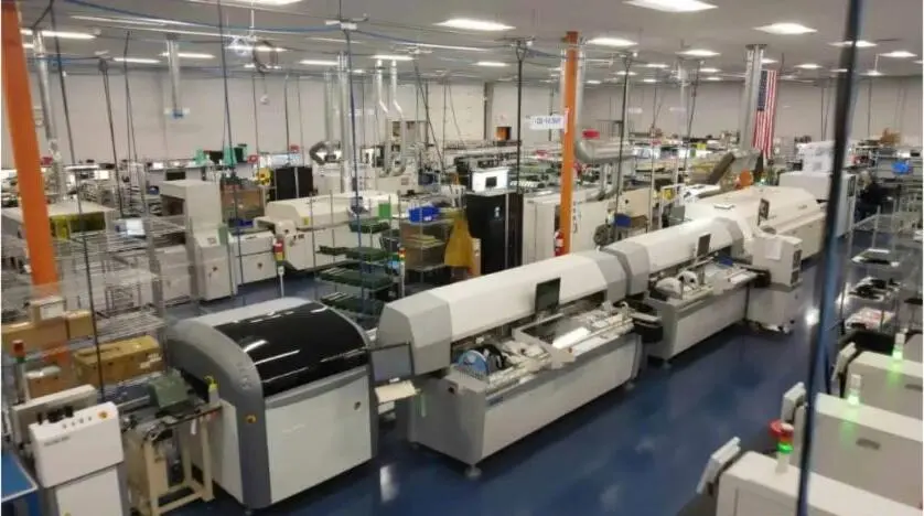
Pro-Active Engineering holds ISO 9001:2015, AS9100, ITAR registration, JCP certification and Nadcap accreditation. All operations run from a single facility in Sun Prairie, Wisconsin.

Decision Checklist for Flip Chip Vibration Programs
Engineering and program managers evaluating a flip-chip assembly partner for vibration-critical applications can use the following checklist as a minimum qualification bar for aerospace and defense programs:
- ITAR registration with documented foreign-national access controls and personnel training records
- AS9100 certification covering design, assembly and test operations
- Nadcap accreditation for applicable special processes
- JCP certification (DD Form 2345) for military program eligibility
- In-house flip-chip assembly capability with process-controlled underfill dispensing and cure
- Board-level vibration testing performed within the same facility as assembly
- Modal-to-fatigue FEA capability with documented simulation-to-hardware correlation
- Full traceability from design revision through production lot and test record
- DFM integration at the design phase, not as a post-layout review
- SAE AS5553B counterfeit avoidance methodology for component sourcing
- NIST 800-171 alignment and CMMC readiness for CUI handling
Connect with the engineering team to review program requirements against this checklist.
Frequently Asked Questions
How does Pro-Active Engineering handle the transition from prototype to production for flip-chip programs?
Prototypes at Pro-Active Engineering are built using the same processes, materials and equipment as production runs. The engineering team that supports the design phase remains involved through production transfer, so process parameters, underfill specifications and test requirements do not need to be re-established by a separate production team. This continuity removes the prototype-to-production disconnect that often causes late-stage manufacturability failures on complex interconnect programs.
What does an integrated workflow mean for total cost of ownership on a vibration-critical program?
Vendor fragmentation creates hidden costs such as design intent lost between firms, rework driven by DFM issues discovered at assembly and qualification failures that require redesign after hardware is built. An integrated workflow embeds DFM, underfill selection and test planning into the design phase and reduces the probability of late-stage failures. The cost of a redesign or field failure in an aerospace or defense program often exceeds the cost of engineering rigor applied early. Pro-Active Engineering’s single-facility model also removes inter-vendor logistics, documentation reconciliation and accountability gaps.
How does Pro-Active Engineering maintain ITAR compliance across design, assembly and test operations?
Pro-Active Engineering is ITAR-registered and maintains compliance procedures for design, assembly and test operations. Design data, assembly documentation and test records for controlled programs are handled within the same compliance framework. The company also maintains NIST 800-171 alignment and CMMC readiness for programs involving controlled unclassified information, so customers avoid managing compliance handoffs between a design firm, an assembler and a test lab.
Can Pro-Active Engineering support combined vibration and thermal testing requirements?
Combined-environment testing requirements, including those derived from MIL-STD-810H, are incorporated into program planning at the design phase. The engineering team evaluates material selections, underfill choices and board construction against the full operational load spectrum before production commitment. Board-level test fixtures and support conditions are designed to match the production assembly configuration, so test results reflect the deployed hardware state rather than a simplified test vehicle.
What is the onboarding process for a new flip-chip program at Pro-Active Engineering?
New programs typically begin with a design review and DFM assessment. The engineering team evaluates the existing design for vibration reliability risk, underfill compatibility and testability before any hardware is built. For programs transferring from another supplier, Pro-Active Engineering can start with a pilot build to validate process compatibility and documentation continuity before full production transfer. The goal is to identify and resolve risk at the earliest possible program phase, not after qualification testing.