
Key Design Takeaways For Sintered Silver CTE
-
Sintered silver CTE typically falls in the 18-20 ppm/°C range and behaves as a process-dependent property, not a fixed constant.
-
Porosity acts as the main tuning lever for effective CTE and also affects thermal and electrical conductivity.
-
CTE mismatch between sintered silver and SiC exceeds a 4:1 ratio and drives significant thermomechanical stress during thermal cycling.
-
Push-rod dilatometry and TMA provide the primary CTE measurements, with results shaped by sample geometry, heating rate and temperature range.
-
Pro-Active Engineering provides silver sintering expertise with direct thermal path technology and full-system integration, supporting reliable high-power assemblies.
Typical CTE Range For Sintered Silver Joints
Sintered silver CTE is typically reported in the range of approximately 18 to 20 ppm per degree C in published literature. Industry packaging references cite values near 19.7 ppm per degree C for sintered silver die attach while analyses of CTE compatibility in SiC assemblies place the range at approximately 19 to 20 ppm per degree C.
This range reflects the porous nature of sintered silver joints. The effective CTE represents a composite response of dense silver metal and distributed voids. Processing route, particle size, sintering temperature, applied pressure and dwell time set the final void fraction and therefore the thermal expansion behavior.
Engineers design to the effective CTE of the sintered joint rather than the handbook value for bulk silver. The gap between joint CTE and bulk silver CTE grows as porosity increases. Research on silver nanoparticle paste systems has reported CTE values that span a wide range depending on sintering environment and confinement conditions, which confirms that joint CTE depends on process conditions.
How Porosity And Sintering Conditions Shape Sintered Silver CTE
Porosity acts as the primary factor that separates the effective CTE of a sintered silver joint from that of bulk silver. Voids in the sintered network accommodate thermal strain locally, so a more porous joint exhibits a lower effective CTE than a dense one. Studies of porous sintered materials such as LPBF-fabricated Invar 36 indicate that porosity is inversely related to effective CTE and that this relationship weakens at higher temperatures as voids lose their capacity to absorb expansion.
Porosity functions as a trade-off lever. Higher porosity lowers effective CTE but also reduces thermal and electrical conductivity. Studies of pressureless-sintered submicron silver flake joints show that porosity falls substantially as peak sintering temperature increases, with corresponding improvements in thermal conductivity and joint shear strength. Because sintering temperature controls how much porosity remains, it often becomes the dominant process variable in many paste systems, while sintering time has a smaller influence.
Applied pressure during sintering accelerates densification and further reduces porosity. A 2026 study by Gharaibeh et al. at The Hashemite University and the University of Freiburg found that higher sintering pressure and extended sintering duration significantly reduced porosity in micro-sized silver particle joints, improving elastic modulus, yield strength and failure strain. Because porosity also governs strain-rate sensitivity in sintered silver, these process differences explain why published CTE and thermomechanical property values vary between studies.
Beyond porosity, filler additions offer another route to tuning effective CTE. Published work on silver paste formulations notes that adding CTE-compatible fillers can improve the reliability of sintered silver joints by shifting the effective expansion coefficient of the joint toward the die or substrate. Ceramic or metallic fillers with lower CTE than silver reduce the composite joint CTE but introduce trade-offs in conductivity and process complexity that require application-specific evaluation.
Paste formulation and particle architecture also influence CTE. Research from the China GRINM Group and GRIMAT Engineering Institute demonstrates that hybrid silver pastes combining flake-shaped micro-silver with nano-silver use the larger flakes as a scaffold while nano-silver sinters around them, improving network density and connectivity in pressureless sintered joints. The resulting microstructure sets the effective CTE of the joint.
Silver sintering CTE mismatch consequences become most severe when process choices that reduce porosity and raise effective CTE are applied to joints between high-CTE sintered silver and low-CTE substrates such as SiC. Clear understanding of the porosity and CTE relationship before locking in a sintering process supports more reliable joint design.
Discuss sintered silver process design with the Pro-Active Engineering team.
Measurement Methods For Sintered Silver CTE
Two primary techniques measure the coefficient of thermal expansion of sintered silver: push-rod dilatometry and thermomechanical analysis (TMA).
Push-rod dilatometry measures linear thermal expansion by tracking sample length change versus temperature under a controlled heating program, with ASTM E831 specifying operating procedures for metals, ceramics and plastics across wide temperature ranges. This method serves as the primary choice when direct dimensional-change measurement is needed for bulk or near-bulk specimens.
TMA measures dimensional change versus temperature under a small non-oscillating load and detects nanometer-scale deformation, which suits thin or small specimens. Common governing CTE testing standards include ASTM E228 for quartz push-rod dilatometers, ISO 11359-2 for plastics and polymer composites and GB/T 4339 for metallic materials.
Measuring sintered silver CTE is harder than measuring bulk silver because porosity, specimen geometry and sintering-induced anisotropy can all bias results. Sample geometry and heating rate strongly affect accuracy. Specimens that are too short reduce precision, specimens that are too long tend to bend and heating rates that are too fast cause thermal lag that inflates the measured CTE.
X-ray diffraction can measure lattice-parameter changes as a proxy for thermal expansion but captures crystallographic expansion rather than macroscopic bulk behavior. XRD measures lattice spacing changes and does not capture porosity, grain-boundary compliance or interparticle sliding, the mechanisms that dominate thermal expansion behavior in porous sintered materials. For sintered silver die-attach joints, dilatometry and TMA provide more appropriate primary methods.
CTE is typically reported as a mean value averaged over a specified temperature range. Engineers review the measurement conditions behind a quoted number because the reported value depends on the temperature range and heating rate. Complementary microstructural imaging that correlates porosity with measured CTE strengthens confidence in reported values.
CTE Mismatch Between Sintered Silver And Common Substrates
CTE mismatch between sintered silver and the die or substrate represents a central reliability concern in power module die attach. Sintered silver exhibits a CTE of approximately 19 to 20 ppm per degree C while SiC substrates demonstrate values around 4.2 to 4.7 ppm per degree C, creating a CTE ratio exceeding 4:1 that drives severe thermomechanical stress during thermal cycling.
Silicon also has a lower CTE than sintered silver, though the mismatch magnitude differs from SiC. Silicon die sits near 2.6 ppm per degree C while AlN substrates are near 4.5 ppm per degree C, which makes AlN a closer match to SiC than to sintered silver and a frequent substrate choice for high-performance SiC modules. Silicon nitride substrates offer an even closer CTE match to SiC and strong thermal shock resistance, which suits applications with severe thermal cycling demands.
The consequences of mismatch are well documented. A 2026 review by Liu et al. at Huazhong University of Science and Technology reports that CTE mismatch between the sintered silver layer and the die or ceramic substrate causes cracks at interface edges during thermal cycling, damaging both the heat dissipation path and the electrical connection. Microcracks typically nucleate at interface corners and edges where stress concentration factors reach maximum values, then propagate through the sintered silver matrix following grain boundaries and porosity networks.
Silver sintering remains attractive despite this mismatch. Sintered silver thermal and electrical conductivity, its ductile joint behavior and its high melting point allow it to outperform conventional solders in high-temperature power cycling when the mismatch is engineered appropriately. Sintered silver die attach provides better thermal fatigue resistance and extends power-cycling lifetime of SiC power modules compared with conventional solder die-attach materials. Joint reliability under thermal cycling depends on how well the design manages accumulated stress from repeated expansion and contraction.
Design Strategies To Manage Sintered Silver CTE Mismatch
Effective management of silver sintering CTE mismatch relies on coordinated material, process and design choices applied early in the program.
Porosity control offers the most direct lever. Tuning sintering conditions to achieve a target porosity level shifts the effective CTE of the joint while also changing thermal conductivity. A more porous joint has a lower effective CTE but conducts heat less efficiently, so the optimal porosity depends on specific thermal and reliability requirements.
Filler additions and composite sinter pastes shift the effective CTE of the joint toward the die or substrate. Published research confirms that adding CTE-compatible fillers can improve the reliability of silver nanopaste joints, although each filler type introduces trade-offs in conductivity and process complexity.
Joint design factors reduce interfacial stress by distributing strain over a larger volume or by introducing compliance between rigid materials. These factors include bond-line thickness, die and substrate metallization and the use of compliant or graded interlayers. Analyses of direct die-attach approaches using SiC-to-SiC bonding with sintered silver demonstrate that near-perfect CTE matching at the die-to-cooler interface substantially reduces thermomechanical stress and improves long-term reliability.
Substrate selection and package architecture set the thermomechanical environment before the sintered silver joint is designed. AlN substrates offer a close CTE match to SiC and order-of-magnitude better thermal conductivity than alumina, while Si3N4 substrates provide an even closer CTE match with strong mechanical strength. Direct thermal path and metal-core constructions change stress distribution across the full assembly stack.
Early thermal-mechanical simulation and design-for-manufacturability reviews reduce the risk of late-stage reliability issues. Identifying dominant stress concentrations in simulation before tooling or process development begins allows iteration on joint geometry and material selection at lower cost.
Start a DFM and reliability review with Pro-Active Engineering for sintered silver power module assemblies.
CTE And Material Trade-Offs For Die-Attach Selection
Sintered silver thermal expansion sits near the upper end of the metallic die-attach range. Conventional tin-based solders typically have CTE values similar to or slightly higher than sintered silver, so substituting solder for sintered silver does not meaningfully reduce mismatch with SiC or Si. Conventional tin-lead or tin-silver-copper solders are unsuitable for the high operating temperatures and stiffness of SiC, and bonding SiC dies to substrates using solder can create localized mechanical stress due to CTE differences.
Epoxy-based die-attach materials vary widely in CTE depending on filler loading and formulation. Highly filled epoxies can achieve lower CTE than unfilled systems, but epoxy die-attach materials generally have lower thermal conductivity than sintered silver, which limits their use in high-power-density applications.
The engineering trade-off extends beyond CTE. Sintered silver offers a combination of high thermal conductivity, a melting point near that of bulk silver and a joint that can sustain high-temperature operation, a property set that solder and most epoxy systems do not provide together. For SiC applications requiring automotive-grade reliability (AEC-Q101) or continuous operation above 150 °C junction temperature, sintered silver die attach is the recommended choice. Material selection follows from application thermal, reliability and compliance requirements rather than CTE alone.
Practical Tips For Thermal-Mechanical Simulation Of Sintered Silver
Once the die-attach material is selected, the effective CTE of the sintered joint becomes a key input to thermal-mechanical simulation. Modeling that joint requires several choices that differ from bulk-metal modeling.
Simulation models should use the effective CTE of the porous sintered joint rather than the bulk silver value. The two differ and the gap depends on porosity. Gharaibeh et al. (2026) validated a bilinear isotropic hardening constitutive model incorporating porosity effects through finite element simulations, providing a modeling framework for reliable design of power electronic assemblies using sintered silver joints.
Temperature-dependent material properties improve accuracy. CTE, elastic modulus and yield strength of sintered silver all vary with temperature, and using room-temperature values across the full operating range introduces non-conservative errors in stress predictions.
Sensitivity studies on porosity and bond-line thickness help identify the dominant drivers of interface stress. These two variables typically control the stress state at the die-attach interface. Understanding which variable governs peak stress in a given geometry guides process and design decisions more efficiently than attempting to tune all variables at once.
Correlation between simulation results, thermal-cycling test data and microstructural inspection strengthens confidence in the model. Simulation inputs should trace back to published literature or measured data, and assumptions should be documented so that future design iterations can be evaluated consistently.
Why Pro-Active Engineering For Silver Sintering And Thermal Management
Pro-Active Engineering serves as an integrated partner for teams that need to move from sintered silver CTE analysis to a manufacturable, reliable power assembly. Founded in 1996 and operating from a 45,000 sq. ft. facility in Sun Prairie, Wisconsin, Pro-Active brings approximately 30 years of experience in the PCB industry and a workforce of more than 120 electronics professionals to each program.
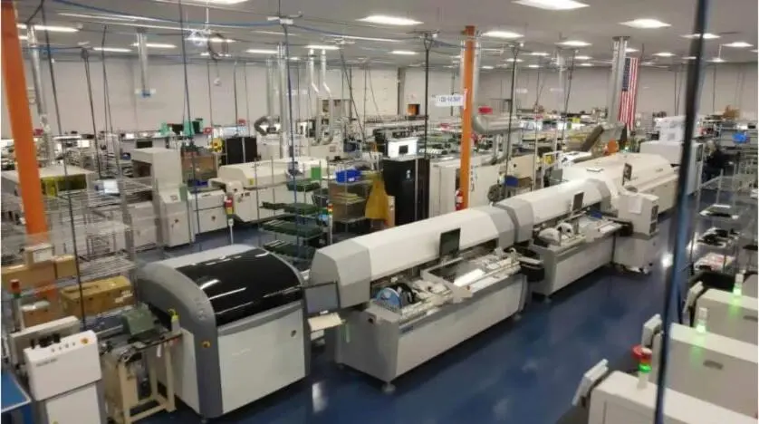
Pro-Active thermal management and high-power capabilities include silver sintering, direct thermal path PCB technology, advanced metal-core constructions, heavy copper integration and integrated dielectric structures under one roof. Interconnect capabilities extend to wire bonding, flip chip assembly and hybrid high-density assemblies engineered for mission-critical performance.
This integrated workflow differentiates Pro-Active from fragmented supply chains. Design and engineering with DFM built in from day one, rapid prototyping through the Speed Shop, PCB assembly, conformal coating and potting, box build and full system integration are managed by a single accountable partner. Processes and quality controls remain consistent from development through production, which supports smooth scaling.

Pro-Active holds ISO 9001:2015, AS9100, ITAR registration, JCP certification and Nadcap accreditation and maintains alignment with NIST 800-171 and CMMC readiness. Defense and aerospace customers rely on Pro-Active documentation discipline, full traceability and assemblies engineered for long service cycles in regulated environments.

For power and energy, industrial, defense and aerospace programs where sintered silver CTE management is a design-critical requirement, Pro-Active delivers engineered thermal solutions that reduce thermal resistance, extend product life and protect performance in high-current applications.

Schedule a discussion on sintered silver and high-power PCB assembly with Pro-Active Engineering.
Conclusion And Next Steps For Sintered Silver CTE Design
Sintered silver CTE typically falls in the 18 to 20 ppm per degree C range reported in published literature, and behaves as a process-dependent property that varies with porosity, sintering conditions and filler additions. Against SiC at roughly 4.2 to 4.7 ppm per degree C, Si at roughly 2.6 ppm per degree C and AlN at roughly 4.5 ppm per degree C, the mismatch is substantial and requires active management through porosity control, composite paste formulations, joint design and substrate selection.
Early thermal-mechanical analysis and DFM integration reduce reliability risk before tooling or process development begins. Teams that understand the porosity and CTE relationship and build that understanding into simulation inputs and process specifications stand in a stronger position to deliver power modules that meet long-service-cycle reliability requirements.
Effective next steps include mapping thermal and reliability requirements against the specific die and substrate combination, evaluating sintering process parameters and paste formulations for their effect on effective CTE and validating the design through prototype builds and thermal-cycling testing before committing to production volumes.
Pro-Active Engineering brings silver sintering, direct thermal path technology, advanced interconnect and full-system integration under one roof, with DFM built in from day one and a quality system built for regulated industries.
Connect with Pro-Active Engineering on sintered silver die-attach and high-power PCB assembly to move from analysis to production-ready hardware.