
Key Takeaways
- Die attach is the foundational step in microsystems packaging and sets mechanical, thermal and sometimes electrical performance for MEMS, sensors, RF and photonic devices.
- Epoxy, eutectic, flip chip and silver sintering each carry specific trade-offs in process temperature, thermal resistance, outgassing and reworkability that must align with device class and application needs.
- Device class drives selection: MEMS and pressure sensors favor low-modulus silicones, RF and microwave devices often need eutectic or silver sintering, and photonic devices depend on low-outgassing adhesives.
- Void control, clear inspection protocols and downstream compatibility with wire bonding and encapsulation prevent delamination, die cracking and thermal fatigue failures.
- Pro-Active Engineering provides integrated die attach, wire bonding, flip chip and silver sintering services under one ITAR-registered, AS9100-certified quality system, and interested teams can request a die attach quote.
Die Attach Fundamentals in Microsystems Packaging
Microsystems in packaging engineering covers microelectronics, photonics and micro-electromechanical systems (MEMS), not a specific brand. Device class sets the engineering constraints, and selecting a method without mapping it to that class often causes die attach reliability failures.
The die attach process follows a defined sequence:
- Die preparation (dicing, cleaning, inspection)
- Substrate preparation and cleaning to remove contamination and raise surface energy
- Adhesive or preform dispense and placement with controlled volume
- Die placement with vision alignment and controlled force
- Cure or reflow per the material specification
- Inspection by X-ray, confocal scanning acoustic microscopy (CSAM) or both
Wire bonding or flip chip bonding follows die attach. Die attach provides mechanical support between the die and substrate and sets the primary thermal path. It also sets electrical performance in some applications.
The die attach material and process choice comes first in the assembly flow and constrains every downstream step. The die must remain attached through wire bonding, overmoulding and solder reflow at 260°C. The choice between conductive and insulating adhesives is the most consequential specification decision and sets the process temperature window for the build.
Those process temperatures vary widely by method. The next section compares the four main die attach approaches and their trade-offs.
Comparing Epoxy, Eutectic, Flip Chip and Silver Sintering
Epoxy die attach runs at lower process temperatures than metallurgical methods. The adhesive absorbs CTE mismatch stress, which suits stress-sensitive devices. Specially formulated epoxies with thermoplastic resins or similar additives can be reworked because the cured adhesive softens at elevated temperature, while conventional thermosetting epoxies cure into insoluble networks that cannot be reworked.
Epoxy has higher thermal resistance than metal-based methods and outgasses organic content, which limits hermetic sealing compatibility. Conventional epoxy die attach adhesives outgas moisture and organic volatiles during curing and therefore do not suit packages that require low internal moisture. Blending a resin that contains an OCN functional group at about 20 percent can reduce moisture outgassing to acceptable levels. Ionic purity also matters. Semiconductor-grade epoxy formulations control chloride content, often below 1 ppm, because mobile ions can migrate under electrical bias and cause electrochemical corrosion of aluminum bond pads and metal traces.
Au-Si eutectic die attach forms a metallurgical bond with much lower thermal resistance than thermoset epoxy adhesive. Thermal simulations show about 0.07 mm²·°C/W for a 14 µm bond line at 200 W/m·K versus about 40.0 mm²·°C/W for a 40 µm bond line at 1 W/m·K. That shift reduces θJA from about 44 to about 36 °C/W in Device A and from about 26 to about 20 °C/W in Device B. Au-Si eutectic die attach is inorganic and exhibits ultra-low outgassing, which suits hermetic ceramic package sealing for high-reliability and space-grade applications. The process runs at higher temperature in a controlled atmosphere, and thermal stress cracks at the die or solder interfaces dominate long-term failures under thermal cycling.
Flip chip places the die face-down and routes electrical connections through an area array of bumps beneath the die rather than through wire bonds above it. Electrical paths become shorter and denser. Process demands tighten because bump uniformity, coplanarity and underfill gap control must stay within specification. Underfill does not appear in every configuration but commonly improves mechanical reliability and manages thermal expansion stresses. Underfill must fully fill the die-to-substrate gap. After cure, it redistributes thermal stresses among the chip, underfill, substrate and all solder joints instead of concentrating them on peripheral joints, which cuts solder strain to about 10–25 percent of unencapsulated joints.
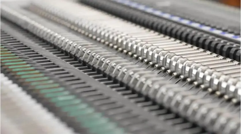
Silver sintering forms an all-metal joint by fusing silver particles into a dense matrix through a solid-state diffusion process. The joint forms without melting or capillary action. Silver sintering reaches thermal conductivity of roughly 150–250 W/m·K, which exceeds silver epoxy die attach adhesives and eutectic gold-tin solder at about 57 W/m·K. Pressure-less silver sintering joints between a Si die and Si3N4 AMB substrate can survive at least 1,500 thermal cycles from -40 °C to 175 °C without shear strength loss, while reference solder strengths drop to about 62–86 percent of initial values.

Silver sintering now appears frequently in wide-bandgap power devices where power density exceeds what conventional solders can handle. Solders sit near 60 W/m·K thermal conductivity and about 300 °C melting point. The silver sintering process window is narrower than epoxy and uses higher process temperatures, typically 200–300°C. Some substrate combinations without surface metallization also require applied pressure, although pressureless sintering is possible with specific materials.
Device-Class Selection Logic for Die Attach
Device class and application drive the choice of die attach method. A low-cost MCU in a QFN package often uses epoxy. A SiC traction inverter die often uses silver sinter. A flip-chip CPU uses solder bumping. The primary decision centers on the required joint function, such as electrical or thermal conductivity, with device class as a key input.
MEMS devices often contain moving elements such as cantilevers, membranes and proof masses and can use stress-sensitive structures to measure deformation. For MEMS die attach that must minimize stress, highly flexible silicones with a Young’s modulus near 1 MPa are standard. Conventional epoxies with high modulus only suit some cases. UV or dual-cure chemistries now see wider use for heat-sensitive MEMS die because the UV cure step occurs near room temperature and avoids the thermal load of full thermal cure cycles. Dual-cure systems may still require a secondary thermal cure near 100–150 °C to complete crosslinking while protecting delicate membrane structures. Eutectic attach supports hermetic cap seals when the higher process temperature is acceptable.
Pressure sensors favor soft silicone adhesives with low hardness and low modulus. Optical and image sensors favor low-outgassing certified adhesives. Hard silicone or epoxy die bonding destabilizes pressure sensor offset and increases the temperature coefficient of offset. For silicon piezoresistive stress sensors, a wafer surface tilted off the crystallographic axes introduces errors in piezoresistive coefficients that affect calibration and extracted stresses. Excess adhesive that reaches a pressure sensor diaphragm or an optical sensor active window dampens mechanical response or blocks the signal path.
GaAs and GaN RF and microwave die often use eutectic AuSn die attach or silver sintering when thermal resistance and low-loss RF grounding dominate. Epoxy die attach remains common and suits low-power devices. In modern GaN devices at power densities of 5.0 W/mm or higher, die-attach voids can raise peak temperature and thermal resistance. The impact depends on void size, percentage, location and style. Voids larger than about 0.15 mm under power FETs cause particular harm, so void minimization becomes a thermal management task as well as a quality metric. Silver-filled conductive epoxy die attach works best at moderate power dissipation, where its thermal conductivity of about 3–10 W/m·K and added thermal resistance relative to solder remain acceptable.
Photonic devices bonded with DVS-BCB (Cyclotene) gain a bonding layer that does not outgas during polymerization. The sub-100 nm layer also provides optical clarity for efficient evanescent coupling between III-V layers and silicon waveguides. Contamination of an optical window or emitter surface from adhesive volatiles degrades performance. In vacuum or space environments, light-absorbing deposits become permanent because the optics cannot be serviced. UV-curable and dual-cure adhesives such as Master Bond UV16 and UV22DC80-10F meet NASA ASTM E595 low-outgassing requirements while curing at temperatures as low as 80 °C. Complete cure is critical, and dual-cure systems address shadowed areas where UV light cannot reach.
Get a die attach consultation to align device class and attach method.
Void Minimization and Die Attach Inspection
X-ray imaging and scanning acoustic microscopy are two of the four common techniques for detecting die attach voids. Cross-section or parallel polishing with optical or electron microscopes and glass die or slide methods complete the set. Two-dimensional projection X-ray provides fast inspection and screens die-attach voids and other obvious defects. It compresses the package into a single projection, so it cannot resolve void depth or exact location and works best when the approximate defect location is known.
C-mode scanning acoustic microscopy in reflection mode maps the bond interface using acoustic impedance contrast and resolves the depth and specific interface of delamination. Through-transmission mode detects delamination but cannot identify the exact interface or depth. It suits subsurface delamination that X-ray cannot distinguish from a solid joint. High-reliability builds often stack inspection methods in sequence. X-ray comes first, with 2D for inline screening and 3D CT for process validation. CSAM or SAM follows when delamination is a concern and often appears in incoming component inspection and post-stress evaluation.
Voiding is a frequent quality issue in die attach. Voids sit below the surface, so visual inspection cannot detect them and X-ray or SAM becomes mandatory. Acceptance depends on the agreed inspection method and written criteria. MIL-STD-883 Method 2030 and IPC standards provide the governing frameworks. Specifications should define void criteria by device class and application and state the inspection method and acceptance criteria in writing before production.
Downstream Compatibility With Wire Bonding and Encapsulation
Die attach choices constrain every downstream step and often set the stage for later reliability issues.
Die attach bond-line thickness and tilt variation directly affect wire bonding. There is a strong correlation between lifted wire bonds and die attach modulus. Low modulus at bonding temperature can cause lifted ball bonds because ultrasonic energy does not couple effectively. A cure schedule tuned for die attach throughput can also conflict with a downstream reflow step if the adhesive glass transition temperature sits near the reflow peak. Glass transition temperature relative to maximum service temperature is a primary adhesive selection constraint. A common guideline keeps at least 20–30°C of margin between maximum application temperature and Tg.
In flip chip assembly, the standoff between die and substrate must support capillary underfill flow. Voids in the underfill layer reduce reliability under thermal cycling by acting as crack initiation points and promoting delamination. The impact depends on void location and underfill properties.
Wire sweep is the deflection of bonded wires caused by encapsulant or molding compound flow during encapsulation such as glob top or molding. It can also occur during bonding or handling. Wire sweep during encapsulation depends on wire loop geometry set during bonding. Loop height is the primary factor, and sweep deflection tracks closely with the ratio of bond height to bond span. Die attach, wire bonding and encapsulation form a connected sequence. A weakness introduced at die attach, such as a die crack from residual stress, can produce electrical failures at many stages of product life.
Cost and Lead Time Drivers for Microsystems Die Attach
Low-volume and high-mix die attach work is dominated by setup and changeover. Every new variant forces the floor to:
- Reload programs
- Swap tooling
- Update inspection parameters
Die-to-wafer and die-to-die process flows suit low-volume and high-mix applications because costs spread across fewer units. Material lot traceability is mandatory in defense contracting under DLAD procurement notes C03 and 11.392 and in medical device manufacturing under FDA 21 CFR 820.65 and ISO 13485 clause 7.5.9. Commercial workflows often operate without those formal traceability rules.
Advanced packaging architectures such as chiplet designs, 2.5D and 3D stacking and high-density fan-out panel packaging increase inspection burden. The number of sub-components to inspect and verify has more than tripled. Decreasing bump and pitch sizes raise demands on metrology and inspection, and new inspection steps appear at each layer as feature size shrinks.
Qualification cycles for new die attach materials such as dicing die attach film can span 6 to 18 months before commercial volumes. Defense and aerospace die attach materials often require qualification that covers die shear, thermal cycling, thermal shock, humidity and moisture resistance, bond strength after thermal aging and outgassing per ASTM E595. When onsemi switched die attach epoxy mid-program, it issued a Product and Process Change Notification and requalified the device against the same product specification, including HTOL and AEC Q100 tests on a 9 mm by 9 mm iBGA vehicle.
Domestic production of silver adhesive pastes for die bonding in the United States remains limited. Current output covers an estimated 25–40 percent of domestic demand. Foreign-sourced material from Japan, South Korea, Germany and the United Kingdom supplies the remaining 60–75 percent. Programs that require domestic material traceability must treat that constraint as a planning input.
Common Die Attach Failure Modes in Microsystems Assemblies
Delamination is the most common adhesive failure mode in sensor die attach. CTE mismatch between die, adhesive and substrate drives interfacial separation that remains invisible at first and grows under thermal cycling. A process that passes initial inspection can delaminate months later if adhesive modulus does not match the CTE difference between die and substrate.
In polymeric die attach adhesives and pastes, voiding can originate from trapped air in the dispense pattern, outgassing during an aggressive cure ramp, insufficient placement force or adhesive viscosity that is too high to flow fully under the die. In sensors, especially power sensors or high-frequency MEMS, voids act as thermal insulators and create hot spots. Those hot spots accelerate adhesive degradation and cause uneven thermal expansion that can lead to die cracking.
Die cracking in die attach often originates from wafer sawing or mechanical stress during the attach process. High and irregular impact force from abnormal die attach machine motion correlates strongly with cracked die frequency. Silicon has a coefficient of thermal expansion of about 2.6 ppm/°C, far below the 12–17 ppm/°C typical of organic substrates and metal lead frames. Specialized lead frame alloys such as Alloy 42 and Kovar sit near 4.5–5.3 ppm/°C. A rigid adhesive transmits CTE mismatch stress into the brittle die instead of absorbing it.
Backgrinding-induced subsurface micro-cracks and residual stress in Si wafers can propagate under later mechanical stress from dicing or thermal-expansion mismatch during packaging. Stress-relief processes such as CMP or dry etching can remove the damaged layer and prevent propagation. A cracked die can pass initial electrical testing and fail after only a few thermal cycles in the field.
Wire bond lift-off can result from contamination or oxidation at the pad or from Kirkendall voiding in gold-aluminum bonds. It can also stem from poor wire bond equipment setup, pad metallization defects, cratering and bond pad peel-off. Kirkendall voiding occurs in gold-aluminum bonds because gold diffuses strongly while aluminum diffusion is negligible. The imbalance drives vacancy fluxes and pore formation at the transition between intermetallic phases. Plasma cleaning with argon or oxygen removes organic contamination and raises surface energy. Oxygen plasma relies mainly on oxidative reactions, while argon plasma cleans by physical sputtering and activation. Both improve die attach wetting and wire bond intermetallic strength.
Under cyclic thermal or power loading, thermal fatigue damage accumulates at the interfacial corners of the die attach layer near the substrate side. The Coffin-Manson relationship states that cycles to failure follow a power-law dependence on plastic strain and forms a base model for low-cycle fatigue in solder-based systems. In practice, engineers often use strain-energy-based models. For thermally activated failure mechanisms, reducing mean junction temperature and thermal cycle swing extends fatigue life.
Screening methods cover several techniques. Die shear testing measures the force required to shear the die and records failure type and residual media appearance. Cross-sectioning exposes the die attach layer to confirm bond-line conditions such as voids after non-destructive SAM inspection, although sample preparation can introduce artifacts. CSAM maps delamination non-destructively. X-ray inspection detects large die-attach voids and coverage issues, while oblique-angle X-ray addresses die tilt. Thermal-cycle qualification and screening force latent workmanship or material defects to surface during controlled testing instead of in the field.
Supplier Qualification Checklist
A supplier qualification for microsystems die attach should verify the following:
- ITAR registration with documented access controls and personnel training
- AS9100 certification issued by an IAQG-accredited Certification Registration Body and listed as current in the IAQG OASIS database
- Lot traceability through raw material, production and shipment records, including material composition disclosure and change control for formulation and raw material source
- Temperature cycling evidence per EN IEC 63215-2:2023 for die attach joint reliability in discrete power electronic devices
- Visual inspection method disclosure per JEDEC JEP142, identified in writing when procuring die
- Documentation control compatible with defense and aerospace program requirements and flow-down of FAR and DFARS requirements to sub-tier suppliers
The domestic specialist landscape for die attach services includes Spirit Electronics, Intech Technologies, Heisler Semiconductor, Palomar Technologies and Microsembly. US-based die attach specialists such as Heisler Semiconductor organize capabilities by process and by equipment. Analog Technologies, a Pro-Active Engineering company, combines wire bonding, silver sintering, die attach and flip-chip, COB and COF assembly in-house under an AS9100-certified, ISO 9001:2015-certified, Nadcap-accredited and ITAR-registered quality system. That structure keeps the thermal path, interconnect and encapsulation decisions within one quality system and reduces handoff risk.

Request a supplier qualification review to align program requirements and certifications.
Pro-Active Engineering Capabilities for Microsystems Die Attach
Pro-Active Engineering, founded in 1996 and based in Sun Prairie, Wisconsin, provides die attach services across MEMS, sensor, RF and photonic device classes. The company offers an integrated set of services under one quality system.
The following services are available under one roof within one quality system:
- Wire bonding
- Flip chip assembly
- Silver sintering
- Direct thermal path technology
Pro-Active Engineering operates within a quality system that includes ISO 9001:2015 certification, JCP certification and ITAR registration, and Analog Technologies holds Nadcap accreditation at its Burnsville, Minnesota facility. The organization employs about 83 people and brings nearly three decades of advanced electronic manufacturing experience to die attach decisions.
The integrated workflow from die attach through wire bonding, flip chip, encapsulation and system integration keeps downstream compatibility constraints with the same engineering team that executes the attach step and supports consistent reliability.
FAQ
How Does Die Attach Differ From Wire Bonding?
Die attach mechanically mounts a singulated die onto a substrate or package and often provides the thermal path that conducts heat away from the die. Wire bonding then creates electrical connections between the die bond pads and the package leads or substrate traces using fine metal wire. Die attach sets die position and alignment and provides the mechanical and thermal bond. Wire bonding depends on that position remaining accurate and stable. Die attach bond-line thickness and tilt variation directly affect wire bonding, and low modulus at bonding temperature can cause lifted ball bonds because ultrasonic energy does not couple effectively. The two steps are sequential and interdependent.
What Are the Common Failure Modes of Die Attach in MEMS and Sensor Assemblies?
Delamination, voiding, die cracking, wire bond lift-off and thermal fatigue appear often in MEMS and sensor assemblies. The primary reliability issues include mechanical fracture, fatigue, creep, stiction, wear and electrical or package-induced failures. Delamination from CTE mismatch is common and deceptive because it passes day-one inspection and grows under thermal cycling.
Die attach solder voiding creates stress concentrators that allow the die to warp and crack, and larger voids lower the force needed to start a crack. In packages such as exposed-pad QFP with large die, CTE mismatch among materials and a high-modulus adhesive transmit stress and warpage into brittle silicon. Backside defects and micro-cracks from wafer fabrication, thinning and dicing act as initiation sites.
Wire bond lift-off can trace to pad contamination or Kirkendall voiding in gold-aluminum bonds, and poor wire bonder setup often plays a role. In power modules, viscoplastic strain and thermal fatigue damage accumulate at the interfacial corners of the die attach near the substrate side during power cycling. Visual inspection alone cannot validate a reliable back-face connection, so programs add die shear testing and, where needed, constant acceleration, X-ray, ultrasound scanning and thermal transient testing.
How Much Does Die Attach Cost for Low-Volume Microsystems Builds?
Setup and changeover dominate cost at low volume. Every new variant requires:
- Tooling changes
- Program reloads
- Inspection parameter updates
Die-to-wafer and die-to-die bonding flows suit low-volume and high-mix applications because costs spread across fewer units. In defense electronics, AS9100-driven MRL alignment makes process repeatability, material traceability and inspection protocol documentation mandatory. Medical programs carry similar traceability and validation overhead. Silver sintering materials cost more than epoxy systems, and qualification cycles for new materials are long. For microsystems, assembly and packaging often account for 80 percent or more of product cost, so total cost reflects engineering rigor and program structure rather than unit count alone.
Can a US Supplier Handle ITAR-Controlled Microsystems Die Attach?
ITAR registration with the Directorate of Defense Trade Controls forms the baseline requirement for any organization that manufactures, exports, temporarily imports or brokers USML-controlled defense articles, including controlled defense microelectronics. Registration is a precondition for licensing or use of ITAR exemptions.
A registered supplier should maintain a documented ITAR compliance program that covers access controls, training records, foreign-national access restrictions and data-handling procedures. DDTC guidelines recommend a Technology Control Plan for organizations that hold technical data and either employ foreign persons or meet with foreign persons frequently. As noted in the supplier checklist, Pro-Active Engineering holds the required ITAR registration and quality certifications that defense and aerospace programs expect for advanced packaging work.
What Is the Difference Between Die Attach and Flip Chip for Microsystems?
Die attach describes the method of securing a die to a substrate, with epoxy, eutectic and silver sintering as common material choices. Flip chip describes an interconnect architecture in which the die sits face-down and connects electrically through an area array of bumps beneath the die instead of wire bonds above it. Flip chip still requires a die attach step at the bump-to-substrate joint plus underfill to distribute CTE mismatch stress.
The two terms describe different aspects of the assembly. Die attach covers how the die is secured. Flip chip covers how it is electrically connected. In microsystems, the choice between wire bond and flip chip interconnect depends on device class, pin count, electrical and thermal performance and cost and occurs at the design stage before attach method selection.
Conclusion: A Decision Checklist for Design Review
Die attach method selection follows a logical sequence. Design for Reliability guidance shows that early reliability decisions prevent expensive fixes later, because correcting a reliability issue during design costs far less than correcting it after launch.
The decision checklist for a design review:
- Identify the device class: MEMS, sensor, RF or photonic
- Define the thermal and stress requirements for that device class
- Select the attach method based on die type and conductivity requirements
- Specify void criteria and inspection method in writing before production
- Verify downstream compatibility for wire bonding standoff, encapsulant flow and reflow conditions
- Qualify the partner for ITAR registration, AS9100 certification, material lot traceability, thermal cycling evidence and inspection method disclosure
Pro-Active Engineering applies that checklist across MEMS, sensor, RF and photonic device classes with wire bonding and flip chip under one ITAR-registered, AS9100-certified roof in Sun Prairie, Wisconsin.
Start your die attach project with the Pro-Active Engineering team.