
Last updated: August 18, 2026
Key Takeaways for Thermal PCB Materials
- Aluminum nitride ceramic leads high-reliability, high-power applications because it spreads heat efficiently, isolates voltage and matches silicon CTE.
- Material selection must balance thermal conductivity with mechanical durability, voltage isolation and solder-joint reliability under thermal cycling.
- Copper-core and aluminum-core MCPCBs support cost-conscious mid-power designs, while high-Tg laminates support multilayer routing and dimensional stability.
- Early DFM integration and specialized manufacturing expertise prevent yield issues when programs move from standard FR-4 to advanced thermal substrates.
- Pro-Active Engineering delivers mission-critical thermal management through an integrated design-to-production workflow; connect with their engineering team to discuss thermal management requirements.
Thermal Conductivity Leaders Among PCB Substrates
Thermal conductivity alone does not define the strongest PCB substrate choice. The material that moves heat fastest must also survive the electrical, mechanical and environmental demands of the application.
Ceramic substrates sit at the top tier of thermal performance among electrically isolating materials. Aluminum nitride spreads heat faster than standard alumina while maintaining dielectric strength suitable for high-voltage power modules. Silicon nitride provides superior fracture toughness, so programs under vibration and mechanical shock often favor it.
Metal-core PCBs present a different trade-off. Copper-core constructions deliver high bulk substrate conductivity, but that figure describes only the metal base layer. The dielectric layer separating the copper base from the circuit traces becomes the limiting factor in the thermal path and carries only a fraction of the base metal conductivity. The dielectric layer in IMS constructions affects the effective thermal path, so the substrate metal spreads heat laterally while the dielectric controls how efficiently heat transfers from the circuit into that base.

High-Tg organic laminates such as polyimide and advanced PTFE-based materials sit below ceramics and MCPCBs in raw thermal conductivity. Standard FR-4 laminates fall well below metal-core and ceramic options in thermal conductivity. High-Tg laminates earn their place in reliability-critical designs through dimensional stability, chemical resistance and compatibility with multilayer routing rather than heat spreading.
Copper vs Aluminum for Heat Conduction in MCPCBs
Copper conducts heat more effectively than aluminum as a bulk material. Copper-core PCBs achieve lower power transistor junction temperatures than equivalent FR-4 boards at the same power dissipation, and copper’s lateral spreading advantage over aluminum becomes clear in high-power-density layouts.
That advantage introduces trade-offs. Copper is denser and heavier than aluminum, which matters in weight-sensitive aerospace and defense programs. Copper-core boards also carry higher material cost. Aluminum-core MCPCBs still deliver meaningful junction temperature reductions over FR-4 at equivalent power levels. They often serve as the practical choice for mid-power LED drivers, motor controllers and industrial power supplies where weight and cost constraints apply.
The dielectric layer governs both constructions. Ceramic-filled epoxy dielectrics in copper-core PCBs deliver thermal conductivity above standard organic dielectrics, though still far below the base metal. Premium dielectric materials narrow that gap further but add cost and processing complexity. The choice between copper-core and aluminum-core depends on power density, weight budget and total cost of ownership, not bulk conductivity alone.
CTE Mismatch and Solder-Joint Fatigue
CTE mismatch drives solder-joint fatigue in thermally cycled assemblies. When the substrate and mounted component expand and contract at different rates, the solder joint absorbs the differential strain. Repeated cycles accumulate that strain and eventually cause cracking or delamination.
Organic laminates expand at rates that differ substantially from silicon and gallium nitride semiconductors. Above the glass transition temperature, Z-axis CTE in typical laminates increases sharply, creating high via-barrel stress that leads to barrel cracking and fatigue failures under repeated thermal cycling. In aerospace and defense environments with wide temperature swings over long service lives, that mismatch often becomes a field failure driver.
Ceramic substrates address this directly. AlN’s CTE closely matches silicon (4.5 vs. 4.2 ppm/°C) but is lower than gallium nitride (6.1 ppm/°C), which reduces mechanical stress at the chip-to-substrate interface during thermal cycling for silicon-based devices. Silicon nitride can provide a close CTE match to silicon, and strong thermal-path efficiency at the substrate level often predicts long-term solder-joint survival.
The bonding process also shapes reliability. Thermal cycling qualification is build-specific; survival depends on the material’s CTE match, bonding process and temperature range of each cycle. Active-metal-braze and direct-bond-copper processes each carry distinct reliability profiles. Strong results come from early engineering collaboration on substrate, bonding method and solder system rather than a late-stage material swap.
Reliability Ranking for Five PCB Material Families
Five material families dominate high-reliability, high-power PCB design, and each presents a distinct reliability profile. The following qualitative ranking addresses brittleness, thermal-path efficiency, processing familiarity, voltage isolation and long-term durability.
- Aluminum nitride ceramic: Leads thermal-path efficiency and voltage isolation. CTE closely matches common power semiconductors and supports long solder-joint life under thermal cycling. It is more brittle than metal-core constructions and requires careful handling and specialized metallization. Processing complexity and cost rank highest among these families, yet mission-critical power applications often justify both.
- Silicon nitride ceramic: Provides a close CTE match to silicon and superior fracture toughness relative to AlN. Silicon nitride with active-metal-braze bonding is preferred for applications under combined vibration and thermal cycling because its fracture toughness outlasts AlN over long service life. Programs often select it when mechanical robustness outweighs peak heat-spreading demand.
- Copper-core MCPCB: Delivers the strongest lateral heat spreading among the metal-core options. Metal-core boards are more appropriate for mid-power circuits and simpler single-layer structures. Processing uses familiar PCB fabrication methods and improves yield predictability. CTE mismatch between the copper base and ceramic or silicon components can still drive solder fatigue in demanding thermal-cycling environments.
- Aluminum-core MCPCB: Serves as the most cost-accessible thermal substrate and suits the mid-power applications discussed earlier. Processing familiarity is high and yield remains predictable. At higher power densities, standard FR-4 may not suffice and metal-core substrates become a practical next step. Voltage isolation depends on the dielectric layer, and CTE mismatch with silicon components accumulates over thermal cycles in high-reliability programs.
- High-Tg laminates: High-Tg materials deliver lower CTE and improved mechanical heat resistance compared with standard FR-4, which supports deliberate reliability margin in multilayer designs. Thermal conductivity remains well below ceramic and metal-core options. As discussed earlier, these materials prioritize dimensional stability and multilayer routing over heat spreading. For sustained high-temperature or aerospace and defense applications, polyimide-based materials provide thermal stability and mechanical endurance.
No single material family leads across all five metrics. The strongest choice depends on power density, operating temperature range, mechanical environment and program-specific reliability requirements.
Start a material-selection review with Pro-Active Engineering’s engineering team for a design and reliability assessment tailored to the program.
Manufacturing Limits and DFM for Thermal Substrates
Material selection extends beyond datasheets and into manufacturing limits. Each substrate family introduces distinct constraints that affect yield, prototype-to-production transition and total program cost.

Ceramic substrates require specialized metallization processes such as direct-bond copper, active-metal-braze or thick-film deposition instead of standard copper lamination. Ceramic PCBs require specialized metallization methods. Brittleness creates handling risks during assembly and depaneling that metal-core constructions avoid. Poor control during AlN manufacturing can lead to warpage, inconsistent thickness and surface defects that become expensive in electronics applications. Early engagement with a manufacturing partner that has direct ceramic processing experience helps prevent costly late-stage redesigns.
Metal-core constructions use more familiar PCB fabrication methods but carry specific DFM requirements. Routing and drilling into a metal core demand tooling and process parameters that differ from standard FR-4 fabrication. Thermal-relief design on power planes requires deliberate attention to prevent cold solder joints during reflow.
Heavy copper integration, common in high-current power designs, introduces additional DFM considerations. Heavy copper lamination demands high-resin-content prepreg adjacent to thick copper layers; standard prepreg provides insufficient resin flow, resulting in voids and delamination. Trace width and spacing rules scale with copper weight, and teams must specify etch compensation early to avoid finished-thickness discrepancies.
High-Tg laminates align most closely with standard PCB fabrication lines, yet multilayer stackups with dense via fields still require careful Z-axis CTE management. FR-4 Z-axis CTE rises sharply above Tg, which can contribute to via-barrel cracking in boards with through-hole vias in multilayer stacks.
Across all three families, prototype-to-production transitions work best when DFM enters at the design phase. Material choices that appear straightforward in simulation often surface yield and assembly challenges at first article. Early collaboration with a manufacturing partner that understands both material science and production compresses that learning curve.
How Pro-Active Engineering Builds Mission-Critical Thermal Assemblies
Pro-Active Engineering operates as a single accountable partner from initial PCB layout through production-ready assemblies. The integrated workflow connects design, DFM, advanced thermal solutions and certified manufacturing under one roof at the Sun Prairie, Wisconsin facility.
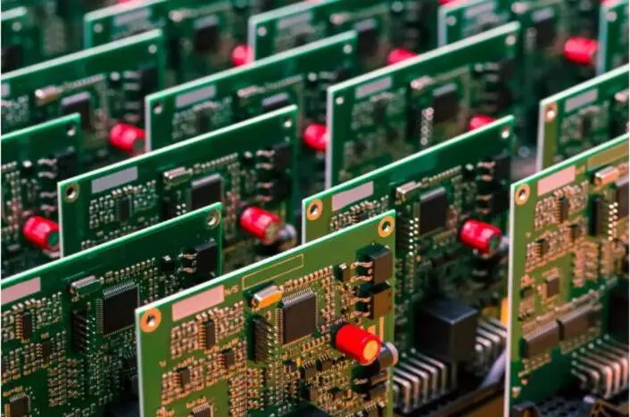
The thermal management capability set covers the full range of high-power substrate requirements. Silver sintering and direct thermal path technology reduce thermal resistance at the die-attach and substrate level. Advanced metal-core constructions and heavy copper integration support high-current designs that exceed the limits of standard laminate builds. Engineering teams incorporate these capabilities during design rather than retrofitting them after thermal failures appear in test.
DFM enters the development process from day one. Pro-Active’s engineering team reviews material selection, stackup, copper weight, via design and component placement before fabrication begins. That review catches manufacturability issues such as dielectric void risk, CTE-driven solder fatigue exposure and etch compensation gaps that often trigger costly late-stage redesigns when separate vendors handle design and manufacturing.
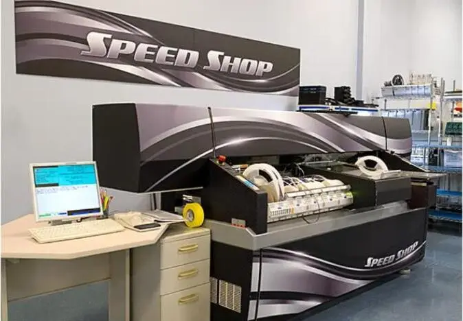
Prototype-to-production continuity forms a structural advantage of this integrated model. Prototypes built through the Speed Shop use the same processes, materials and quality controls as full production runs. Designs that pass in development scale directly into manufacturing without process translation risk.
Aerospace and defense programs benefit from this compliance infrastructure. Pro-Active holds AS9100 certification, Nadcap accreditation and ITAR registration. The facility operates with access controls, data-handling procedures and documentation practices aligned with ITAR requirements. Full traceability and disciplined documentation support audit and program-review requirements for regulated programs.
ISO 9001:2015, IPC-A-610 Class 3 workmanship standards and J-STD-001 soldering standards govern every assembly. SAE AS5553B counterfeit-avoidance methodology and SiliconExpert BOM scrubbing protect against component lifecycle risk. This environment supports long-service-cycle reliability, not just first-article performance.
Start a design review with Pro-Active Engineering’s thermal management and DFM specialists.
Conclusion: Matching PCB Materials to Reliability Goals
Material selection for high-thermal-conductivity PCBs functions as a reliability decision as much as a thermal decision. Aluminum nitride ceramic leads most high-power, high-reliability applications where CTE matching and long solder-joint life rank as priorities. Silicon nitride supports programs where mechanical robustness under vibration sets the main constraint. Copper-core and aluminum-core MCPCBs serve mid-power applications where processing familiarity and cost accessibility matter. High-Tg laminates anchor multilayer designs where routing density and dimensional stability drive the requirement set.
Each choice carries manufacturing constraints that teams must address before finalizing the design. CTE mismatch, dielectric thermal resistance, copper weight DFM rules and bonding process selection all determine whether a thermally strong material delivers a reliable assembly in production.
Pro-Active Engineering integrates material expertise, advanced thermal solutions and DFM into a single workflow that reduces program risk from the first design review through volume production. The team serves aerospace, defense, power electronics and industrial programs that require mission-critical reliability, domestic manufacturing and full compliance traceability.
Engage Pro-Active’s engineering team for a thermal management and material-selection design review.
Frequently Asked Questions
When should a design engineer choose aluminum nitride ceramic over a metal-core PCB?
Aluminum nitride ceramic becomes the stronger choice when a design requires both high thermal conductivity and full electrical isolation in a single substrate layer. That requirement appears frequently in high-voltage power modules where the dielectric layer of a metal-core board would limit voltage isolation. AlN’s CTE also closely matches common power semiconductors, which reduces solder-joint fatigue in assemblies subject to repeated thermal cycling. Metal-core constructions fit mid-power applications where cost, weight and processing familiarity set the primary constraints and voltage isolation requirements remain within the range that a standard dielectric layer can handle.
What DFM issues most often appear when programs move from FR-4 to metal-core or ceramic substrates?
Tooling, thermal-relief design and dielectric selection cause the most common issues. Metal-core boards require drilling and routing into a conductive base, which demands different tooling parameters than standard FR-4 fabrication. Thermal-relief spokes on power planes must be designed deliberately to prevent cold solder joints during reflow. Ceramic substrates add complexity because they require specialized metallization methods instead of standard copper lamination, and brittleness creates handling risks during assembly and depaneling. Early engagement with a manufacturing partner that has direct experience in the target substrate family remains the most effective way to prevent these issues at first article.
How does Pro-Active Engineering support programs that need rapid prototyping and long-term production reliability?
Pro-Active Engineering’s Speed Shop delivers fast-turn prototypes using the same processes, materials and quality controls applied in full production runs. That continuity removes the process translation risk that often creates yield surprises when a design moves from a prototype shop to a production contract manufacturer. DFM enters at the design phase, so material selection, stackup, copper weight and via design receive review before fabrication begins. Programs that start with a prototype and scale to production remain within a single workflow, with full traceability and documentation maintained throughout.
What certifications support Pro-Active Engineering’s aerospace and defense thermal management work?
Pro-Active Engineering holds AS9100 certification, Nadcap accreditation and ITAR registration. The facility operates under ISO 9001:2015 quality management, IPC-A-610 Class 3 workmanship standards and J-STD-001 soldering standards. JCP certification and alignment with NIST 800-171 support programs with controlled unclassified information handling requirements. SAE AS5553B counterfeit-avoidance methodology and SiliconExpert BOM scrubbing integrate into the sourcing process. These credentials collectively support the documentation, traceability and compliance requirements of regulated aerospace and defense programs.
Is silicon nitride a better choice than aluminum nitride for vibration-intensive defense applications?
Silicon nitride often becomes the preferred choice in applications where vibration and mechanical shock act as primary failure drivers alongside thermal cycling. Silicon nitride’s fracture toughness exceeds AlN’s, so it is less likely to crack under combined mechanical and thermal stress over a long service life. AlN delivers stronger raw thermal conductivity, which makes it the better choice when heat spreading dominates and the mechanical environment remains less severe. The right selection depends on the specific combination of power density, thermal cycling range, vibration profile and service life requirements for the program. Pro-Active Engineering’s engineering team evaluates those constraints during the design review process and recommends the substrate that best balances all reliability drivers.