
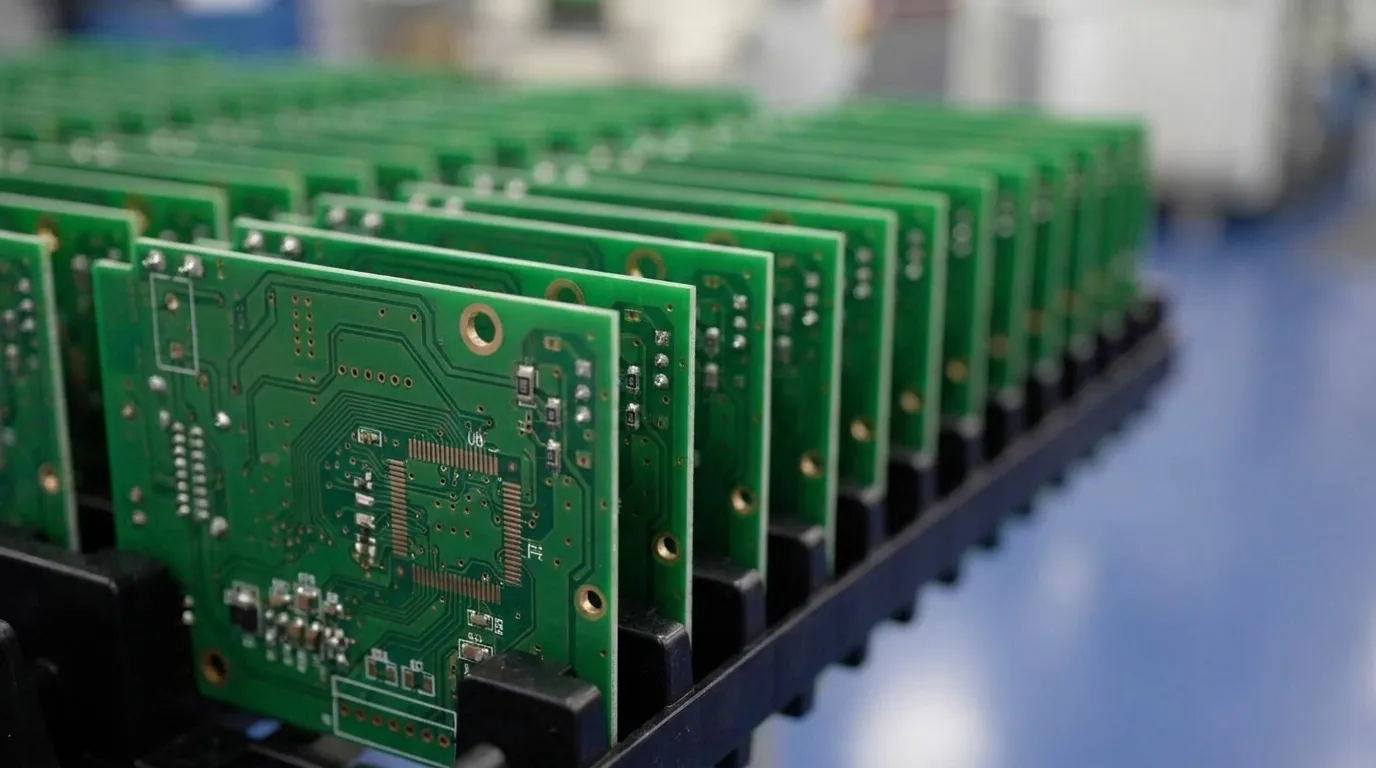
Key Takeaways for Aerospace PCB Assembly
-
High-reliability aerospace PCB assembly depends on strict IPC-A-610 Class 3 workmanship and AS9100 quality management to maintain performance under vibration, thermal cycling and long mission life.
-
Critical technical requirements include minimum 75% barrel fill, 1 mil copper plating with zero voids and extensive inspection methods such as AOI, X-ray and environmental stress testing.
-
Thermal management strategies such as heavy copper, thermal vias and advanced materials lower failure rates and extend product life in high-power aerospace applications.
-
ITAR-compliant domestic manufacturing with AS9100 certification supports counterfeit avoidance, configuration control and full traceability for regulated aerospace programs.
-
Pro-Active Engineering provides integrated DFM, prototyping, Class 3 assembly and validation testing, enabling direct collaboration with its aerospace team on complex program requirements.
IPC-A-610 Class 3 Requirements for Aerospace PCBAs
IPC-A-610 Class 3 is required for aerospace, defense and safety-critical electronics where failure is unacceptable and continuous reliable operation under demanding conditions is mandatory. The standard defines acceptance criteria for solder joints, component mounting and cleanliness that exceed Class 2 at every level.
For through-hole components, minimum barrel fill must be 75% with no exceptions permitted. This barrel fill requirement works with circumferential solder wetting to form a complete electrical and mechanical connection. Circumferential solder wetting on the destination side must cover at least 270 degrees around the barrel wall and component lead. These solder joints depend on robust copper plating. Copper plating thickness must reach 1 mil with zero voids permitted. Adequate pad geometry supports this structure. Minimum internal annular rings must be 1 mil and external annular rings 2 mil, with no lifted or fractured rings accepted.
Class 3 workmanship requirements prioritize complete wetting, proper solder fillet geometry and robust mechanical support of components to enhance resistance to vibration and thermal cycling stresses. These workmanship rules pair with expanded inspection coverage. Inspection methods are more extensive and include visual inspection, AOI, X-ray, microscopic analysis, advanced electrical testing and environmental stress testing such as thermal cycling and vibration testing.
IST testing with D coupons requires the coupon to withstand a minimum of 300–500 thermal cycles before any change in resistance to validate plating integrity. Daisy-chain resistance measurements after reflow simulations and thermal shocks per IPC-TM-650 identify plating voids, thin copper, cracked barrels and interplane separation.
Pro-Active Engineering builds to IPC-A-610 Class 3 across its production lines, with 100% automated optical inspection and X-ray capability integrated into every aerospace program. Engineering teams can engage Pro-Active Engineering early to align Class 3 requirements with program goals and schedule.
Thermal Management Strategies for Aerospace PCB Assemblies
Thermal management sets the baseline for long-term reliability. A common rule derived from the Arrhenius equation states that every 10°C increase in operating temperature roughly doubles the failure rate due to accelerated degradation processes such as electromigration, dielectric breakdown and solder fatigue. Effective thermal design directly reduces that failure rate over the mission profile.
Increasing copper weight improves lateral heat spreading and serves as a direct thermal-management design rule for higher-power assemblies. Maximizing coverage of ground and power planes allows these large copper areas to function as heat spreaders. Connecting multiple internal ground planes with stitching vias increases thermal mass and pulls heat away from localized hotspots.
Thermal vias should be placed directly inside or as close as possible to the thermal pad of surface-mount components to improve heat transfer to inner layers or the board underside. Via-in-pad technology, where vias are filled with epoxy and capped with copper, prevents solder wicking during reflow while providing optimal thermal performance.
For high-reliability designs, IPC-2152 is the recommended physics-based standard for determining current-carrying capacity, as it accounts for thermal conductivity, board stackup and layer differences more accurately than IPC-2221. Thermal validation during prototype builds should include camera-based measurement such as FLIR imaging to confirm the thermal model against real hardware.
Pro-Active Engineering’s thermal management capabilities include silver sintering, direct thermal path PCB technology, advanced metal-core constructions and heavy copper integration, all focused on reducing thermal resistance and extending product life in high-power aerospace applications.
Vibration Resistance and Ruggedization in Aerospace PCB Assembly
Mechanical integrity under vibration forms another core pillar of aerospace reliability. Thermal management addresses temperature stress, while vibration control protects joints and structures from mechanical fatigue. Ruggedization begins at the design stage and extends through assembly and environmental stress screening.
Conformal coating provides a foundational ruggedization technique. Aerospace PCB assemblies should use conformal coatings such as acrylic, silicone, urethane or parylene to protect against moisture, contaminants and electrical failures. Coating selection influences vibration damping, dielectric protection and long-term adhesion under thermal cycling.
Component placement, adhesive staking and underfill add further mechanical reinforcement. High-mass components require additional mechanical support to prevent solder joint fatigue under sustained vibration loads. Beyond the inspection methods described earlier, Class 3 programs add stress, pressure and burn-in testing, along with micro-section analysis.
Environmental stress screening performed before delivery identifies latent defects that would otherwise surface in the field. Pro-Active Engineering integrates conformal coating, potting and ruggedization into its assembly workflow, maintaining process continuity from design through final test.
Material and Coating Choices for Mission-Critical PCBAs
Aerospace-grade laminates must exhibit low Z-axis CTE, high glass-transition temperature, high decomposition temperature, low moisture absorption, low outgassing characteristics and controlled dielectric constant to ensure reliability under extreme thermal and vacuum conditions.
Common aerospace-grade laminate materials include polyimide, which offers the highest thermal stability for extreme environments. When cost constraints favor FR-4 derivatives, materials such as Isola FR408HR, Isola P95 and Isola FR370HR provide improved thermal performance over standard FR-4. For high-frequency applications, Rogers RO4003C delivers controlled dielectric properties. Nelco N7000-2HT supports programs that need a balance of thermal stability and electrical performance. All these materials share low outgassing characteristics measured against ASTM E595.
Parylene conformal coatings are widely used in high-reliability aerospace PCB assemblies due to their uniform coverage and low outgassing properties that protect against moisture and contaminants in vacuum environments. ENIG and ENEPIG surface finishes are recommended for aerospace PCBs to improve solderability, extend shelf life and prevent outgassing issues.
Validation Testing Protocols for High-Reliability PCBAs
Validation testing confirms that an assembly meets its performance specification before delivery. The following test categories form a cohesive validation suite, with each one targeting a specific failure mode.
Thermal cycling validates solder joint and laminate integrity across temperature extremes per IPC-TM-650 and IPC-6012FS. Vibration and shock testing confirm mechanical robustness of joints, coatings and component attachment per MIL-STD-810. X-ray inspection detects internal voids, bridging and BGA joint defects non-destructively. AOI and microsection analysis verify solder fillet geometry, plating thickness and barrel fill against Class 3 workmanship criteria. Functional and ICT testing confirm circuit performance and electrical integrity to program-specific requirements. Outgassing and contamination testing validate material compliance for vacuum or sealed environments per ASTM E595 and NASA-STD-8739.1B. Traceability documentation captures lot data, process parameters, inspection results and operator records under the AS9100 quality system.
ITAR-Compliant Domestic Manufacturing Advantages
Aerospace programs subject to International Traffic in Arms Regulations depend on manufacturing partners with ITAR registration and documented controls over technical data, personnel access and production processes. Offshore production introduces IP exposure, counterfeit component risk and supply chain latency that domestic manufacturing avoids.
AS9100 requires PCB assembly manufacturers to implement dedicated processes for screening and quarantining suspect counterfeit components before they reach the assembly line. Pro-Active Engineering uses SAE AS5553B counterfeit avoidance methodology and SiliconExpert for BOM scrubbing and component lifecycle risk mitigation.
Domestic production also supports configuration control. Under AS9100, every board must match the exact approved design revision with unauthorized part substitutions strictly prohibited. A single-location, ITAR-registered facility simplifies audit trails and reduces the risk of unauthorized design changes across a distributed supply chain.
Pro-Active Engineering is ITAR registered, AS9100 certified, JCP certified and Nadcap accredited, operating from a centralized facility in Sun Prairie, Wisconsin. Program teams can collaborate with Pro-Active Engineering to align ITAR-compliant manufacturing with schedule, cost and risk objectives.
DFM Integration to Prevent Late-Stage Failures
Early DFM engagement prevents costly late-stage manufacturability failures in aerospace programs. Redesigns, re-qualification cycles and schedule delays compound when design and manufacturing operate as separate phases.
DFM reviews should cover component placement optimization, thermal management, test point accessibility and process compatibility, with in-process verification such as AOI, X-ray, ICT and SPC to detect defects and process drift. When these reviews occur during the design phase rather than at first article, correction costs remain far lower than in production.
Over 60–70% of SMT defects originate from solder paste printing, making early process planning, not inspection alone, the most effective defect-prevention strategy. DFM that accounts for paste release, aperture geometry and stencil design reduces this failure mode before a single board is built.
Pro-Active Engineering integrates DFM into the design phase through a unified engineering and manufacturing workflow. Prototypes are built using full production processes, so validated designs move into volume manufacturing without process translation risk.
How Pro-Active Engineering Supports Aerospace PCB Assembly Programs
Pro-Active Engineering is a Wisconsin-based PCBA manufacturer founded in 1996, serving aerospace, defense, space and medical programs from a single 45,000-square-foot facility. The company builds to IPC-A-610 Class 3 and J-STD-001 standards under a certified quality system.
The integrated workflow spans PCB design and engineering, rapid prototyping, SMT and through-hole assembly, conformal coating and potting, box build and system integration, and advanced interconnect and packaging, including wire bonding, flip chip assembly and hybrid high-density assemblies. Thermal management solutions include silver sintering, direct thermal path technology and advanced metal-core constructions.
AS9100 mandates a formal, documented First Article Inspection process to verify that manufacturing setup can consistently meet engineering specifications before full production begins. Pro-Active Engineering’s quality system includes FAI, lot-level traceability, SPI, AOI, X-ray, functional testing and full documentation control managed through Manex ERP for real-time operational visibility.
Programs that start with prototyping through the Speed Shop transition to production using the same processes, equipment and quality controls, which removes the prototype-to-production disconnect that creates reliability risk in fragmented supply chains.
Frequently Asked Questions
What traceability documentation does an AS9100-certified PCB assembler provide for aerospace programs?
AS9100-certified assemblers maintain lot-level or serial-number traceability for all components and assemblies. Documentation packages typically include material certifications, component lot records, reflow and soldering process parameters, AOI and X-ray inspection results, operator identification for each operation, rework records and final test data. This documentation supports root-cause analysis, configuration audits and regulatory compliance throughout the program lifecycle.
How does IPC-A-610 Class 3 differ from Class 2 for aerospace solder joint acceptance?
Class 3 applies stricter acceptance criteria at every inspection point. Barrel fill minimums are higher, annular ring requirements are tighter, copper plating voids are not permitted and solder wetting must cover a greater circumference of the barrel and lead. Defects such as solder voids, cracks and component placement imperfections that may be acceptable under Class 2 are rejectable under Class 3. Inspection methods also expand to include X-ray, microsection analysis and environmental stress testing.
What laminate materials are appropriate for aerospace PCB assemblies exposed to thermal cycling?
Aerospace programs require laminates with high glass-transition temperature, high decomposition temperature, low Z-axis coefficient of thermal expansion, low moisture absorption and low outgassing characteristics. Polyimide is widely used for its thermal stability and reliability under repeated temperature changes. Other materials such as Isola FR408HR, Rogers RO4003C and Nelco N7000-2HT are selected based on the specific thermal, electrical and outgassing requirements of the application. Material selection should be confirmed during the DFM phase to ensure compatibility with the assembly process and end-use environment.
What validation tests are required before delivering a high-reliability aerospace PCBA?
Standard validation for aerospace PCBAs includes thermal cycling, vibration and shock testing, X-ray inspection, AOI, microsection analysis, functional testing and in-circuit testing. Programs with vacuum or sealed-environment requirements add outgassing and contamination testing per ASTM E595. All test results, process parameters and inspection records are captured in a traceability package that supports AS9100 configuration control and program audit requirements.
Can a single domestic partner manage design through production for a complex aerospace PCB program?
An integrated domestic partner with engineering, prototyping, assembly, coating, testing and system integration under one roof can manage the full program lifecycle. This model eliminates vendor fragmentation, maintains configuration control across every phase and ensures that prototypes are built using production-equivalent processes. For regulated aerospace programs, a single accountable partner with AS9100 and ITAR certifications reduces compliance gaps and simplifies the audit trail from design release through final delivery.
Conclusion: Building Reliable Aerospace Electronics with an Integrated Partner
High-reliability aerospace PCB assembly requires alignment across standards compliance, material selection, thermal and mechanical design, validation testing and quality management. IPC-A-610 Class 3 defines the workmanship floor. AS9100 governs the quality system. ITAR registration secures the supply chain. These elements work together most effectively when a single accountable partner manages them as one system.
Engineering teams that engage an integrated domestic partner early in the program, one that brings DFM, advanced interconnect, thermal management and full traceability into a single workflow, reduce the risk of late-stage failures, compliance gaps and schedule overruns common in fragmented supply chains.
Pro-Active Engineering delivers that integrated capability from design through production, supported by AS9100, ITAR, Nadcap and IPC-A-610 Class 3 compliance. Program leaders can connect with Pro-Active Engineering’s aerospace PCB assembly team to align technical requirements, risk profile and production strategy.