
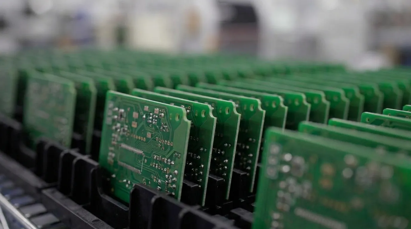
Key Takeaways for Die Attach and Wire Bonding
-
Die attach mounts semiconductor dies to substrates, and wire bonding creates electrical connections that support high-reliability PCB packaging.
-
The sequence includes substrate prep, material application, die placement, thermal curing and staged inspection to confirm bond integrity.
-
Three primary die attach methods, epoxy, eutectic and silver sintering, offer distinct thermal and mechanical benefits for specific applications.
-
Wire bonding techniques such as ball and wedge bonding, combined with gold, aluminum or copper wire, balance performance, cost and environmental demands.
-
Pro-Active Engineering integrates die attach and wire bonding in a single ITAR-registered workflow that reduces vendor handoff risk and maintains full traceability from prototype to production, and the team supports advanced interconnect needs through this unified process.
Step-by-Step Die Attach and Wire Bonding Sequence
Die attach and wire bonding follow a defined sequence inside the broader PCB assembly flow. Each step sets conditions that influence the next step, so process integration has a direct impact on final reliability.
-
Substrate preparation: The substrate is cleaned and inspected to confirm surface condition and pad geometry meet process requirements.
-
Die attach material application: Adhesive, solder or sintering paste is dispensed onto the die attach pad in a controlled pattern.
-
Die placement: The semiconductor die is placed onto the attach material with precision alignment equipment.
-
Cure or reflow: The assembly runs through a controlled thermal cycle to cure the adhesive or form the metallurgical bond.
-
Post-attach inspection: Bond line uniformity, void content and die alignment are verified before the process advances.
-
Wire bonding: Fine wire interconnects form between the die bond pads and the substrate or lead frame using ball or wedge bonding techniques.
-
Wire bond inspection: Pull and shear testing, along with automated optical inspection, confirm bond integrity.
-
Encapsulation or glob top: A protective compound covers the die and wire bonds to shield them from mechanical and environmental stress.
-
Integration into full PCB assembly: The packaged assembly enters Pro-Active Engineering’s SMT and through-hole workflow, which can include conformal coating, functional testing and box build.
Die Attach Methods and Bond Line Control
High-reliability assemblies rely on three primary die attach methods, each with specific thermal and mechanical behavior.
Epoxy die attach uses a filled polymer adhesive that supports a wide range of substrate materials and die sizes. Epoxy suits programs that prioritize process simplicity and material compatibility. Bond line thickness requires tight control because variation changes thermal resistance and shifts mechanical stress across the die.
Eutectic die attach forms a metal alloy bond between the die backside metallization and the substrate. This interface provides low thermal resistance and strong mechanical integrity. It often supports high-power and high-frequency designs that run at elevated thermal loads.
Silver sintering creates a porous silver matrix bond at relatively low process temperatures. The sintered interface delivers thermal and electrical conductivity that surpass many conventional adhesives. Pro-Active Engineering includes silver sintering in its thermal management and high-power PCB solutions for designs where heat dissipation sets the primary constraint.
Bond line thickness functions as a key DFM variable across all three methods. Inconsistent thickness introduces thermal gradients and mechanical stress concentrations that reduce long-term reliability. Pro-Active Engineering’s engineering team addresses bond line control during the design phase before die placement begins.
Wire Bonding Techniques and Material Choices
Once the die is attached and inspected, the next step establishes electrical connections through wire bonding. Two primary techniques support this work, ball bonding and wedge bonding.
Ball bonding uses thermosonic energy. A ball forms at the first bond and a wedge at the second. Gold and copper serve as common wire materials. This technique supports high-volume IC packaging and fine-pitch pads.
Wedge bonding uses ultrasonic or thermosonic energy, and wedges form at both bonds. Aluminum and gold serve as common wire materials. This technique supports power devices, low-temperature substrates and aluminum pad interfaces.
Gold wire provides strong corrosion resistance and consistent bonding behavior. It remains a standard choice in defense and aerospace programs that require long service life and stable electrical performance.
Aluminum wire appears extensively in power device packaging. Its lower cost and compatibility with aluminum bond pads make it practical for wedge bonding. Aluminum also avoids gold-aluminum intermetallic formation when that mechanism threatens reliability.
Copper wire offers higher electrical and thermal conductivity than gold at lower material cost. Copper wire bonding requires tighter process control to manage oxidation and harder bond formation. It now supports many high-reliability packages where performance-to-cost ratio drives program decisions.
Process parameters such as bonding force, ultrasonic energy, temperature and loop geometry directly influence bond strength and long-term reliability. Pro-Active Engineering establishes and validates these parameters inside its quality management system before production begins.
Common Defects and How Pro-Active Prevents Them
Defects in die attach and wire bonding respond well to disciplined process control and early DFM engagement. The most common failure modes appear below with their impact and prevention strategies.
Voids in die attach result from outgassing, contamination or dispensing inconsistency. These voids disrupt the thermal path and create local hot spots that stress the die. Controlled dispense patterns, vacuum reflow and pre-attach surface inspection reduce this risk and stabilize junction temperature.
Non-stick bonds in wire bonding result from contaminated pad surfaces or incorrect bonding parameters. These weak bonds threaten both signal continuity and power delivery. Surface cleanliness protocols, parameter optimization and pull or shear testing confirm bond strength before assemblies move forward.
Wire sweep results from excessive mold compound flow velocity during encapsulation. Swept wires can short or change loop geometry. Loop geometry control, encapsulant viscosity management and post-mold X-ray inspection limit sweep and confirm internal structure.
Cratering results from excessive bonding force on brittle pad metallization. This damage weakens the pad and can propagate into the underlying structure. Force calibration and substrate material review during DFM align bonding parameters with pad robustness.
Lifted die results from insufficient cure or bond line contamination. A lifted die breaks the thermal and mechanical path and often appears as intermittent field failure. Cure profile validation and substrate cleanliness verification address this risk before assemblies leave the line.
Inspection methods include automated optical inspection, scanning acoustic microscopy for void detection in die attach and destructive pull and shear testing on sample bonds. Pro-Active Engineering applies these controls inside its Nadcap-accredited quality system, which maintains full traceability from incoming material through final assembly.
Thermal and Electrical Roles of Die Attach and Wire Bonds
Die attach forms the primary thermal path from the semiconductor junction to the substrate. The thermal resistance of this interface directly sets junction temperature under operating load. Higher junction temperatures accelerate electromigration, intermetallic growth and fatigue cracking. Attach material selection and bond line quality provide the most direct tools for managing this thermal behavior.
Wire bonds carry signal and power between the die and the circuit. Wire length, loop height and wire diameter influence parasitic inductance and resistance. In high-frequency and high-power designs, these parasitics affect signal integrity and power delivery efficiency. Pro-Active Engineering’s engineering team evaluates these parameters during design review and folds interconnect geometry into the broader electrical performance model.
Integrated Workflow for PCB Assembly and Interconnect
Die attach and wire bonding operate as linked steps inside a larger assembly sequence that also includes substrate fabrication, SMT placement, through-hole assembly, conformal coating, functional testing and box build. When separate vendors manage these steps, each handoff introduces risk through documentation gaps, process mismatches and unclear accountability that often surface late in a program.
Pro-Active Engineering manages the complete sequence at its 45,000-square-foot facility in Sun Prairie, Wisconsin. The same quality management system that governs SMT assembly also governs die attach and wire bonding. DFM review occurs before design release, not after defects appear in production. Rapid prototyping through the Speed Shop uses the same processes as full production runs so successful prototypes transfer cleanly into volume manufacturing.
Defense, aerospace and medical programs benefit from this integration because it closes compliance gaps that emerge when regulated processes spread across multiple suppliers. Teams that require this integrated approach can connect with Pro-Active Engineering to review program requirements and map them into a single workflow.
When Flip Chip Becomes the Better Fit
Flip chip assembly inverts the die and connects it directly to the substrate through solder bumps, which removes the need for wire bonds. This structure shortens interconnect length, lowers parasitic inductance and supports higher I/O density in a smaller footprint. It suits applications where signal speed, package size or I/O count exceed the practical limits of wire bonding.
Wire bonding still offers advantages in cost, reworkability and process flexibility. It supports a wider range of die and substrate combinations and does not require wafer-level bumping infrastructure. Many defense and aerospace programs continue to favor wire bonding because its failure modes are well characterized and its inspection methods are mature.
Pro-Active Engineering supports both wire bonding and flip chip assembly. This range allows the engineering team to recommend an approach that aligns with program density, cost and reliability targets without a vendor change.
Reliability, Compliance and Single-Source Accountability
In regulated industries, reliability depends on documentation and traceability. Every material lot, process parameter set and inspection result must connect to the finished assembly. This traceability supports failure analysis, field returns and audits under ISO 9001:2015, AS9100 and Nadcap.
Pro-Active Engineering holds ISO 9001:2015 and AS9100 certifications, Nadcap accreditation, ITAR registration and JCP certification. These frameworks define how die attach and wire bonding processes are documented, controlled and verified. ITAR registration confirms that controlled technical data for defense-related assemblies is handled under access controls and documentation practices that meet DDTC requirements.
For program managers, a single certified partner that manages the full assembly sequence produces one coherent quality record. Splitting the process across vendors creates fragmented records and shared accountability that complicate audits and failure investigations. Programs that require this level of traceability and single-source accountability can connect with Pro-Active Engineering’s team to align compliance requirements with the integrated process.
Frequently Asked Questions
What is the difference between die bonding and wire bonding?
Die bonding, also called die attach, mounts a semiconductor die onto a substrate with an adhesive, solder or sintered material. Wire bonding follows that step and creates electrical connections between the die bond pads and the surrounding circuit using fine metal wire. Die bonding establishes the mechanical and thermal foundation. Wire bonding establishes the electrical interconnect. Precision in both steps supports the reliability of the finished assembly.
Which wire bonding material suits defense and aerospace applications?
Material selection depends on operating environment, pad metallization, frequency and power level. Gold wire offers stable, corrosion-resistant performance and appears widely in long-service-life applications. Aluminum wire appears often in power devices and works well with aluminum bond pads. Copper wire provides strong electrical and thermal performance and supports programs where material cost and conductivity carry significant weight. DFM review aligns these options with program requirements before a process is selected.
How does die attach quality affect long-term board reliability?
Die attach quality sets the thermal resistance between the semiconductor junction and the substrate. Voids, inconsistent bond line thickness or poor adhesion increase thermal resistance, raise junction temperatures and accelerate fatigue cracking and delamination. In high-power or thermally demanding designs, weak die attach performance can shorten service life. Attach material selection, dispense consistency, cure profile control and post-attach inspection work together to manage this risk.
What inspection methods verify die attach and wire bond integrity?
Inspection methods include automated optical inspection for visual defects and scanning acoustic microscopy to detect subsurface voids in the die attach layer. Destructive pull and shear testing on wire bond samples verify bond strength. X-ray inspection evaluates wire sweep and internal geometry after encapsulation. These methods operate inside a documented quality system that maintains traceability from incoming materials through final assembly.
Why does vendor fragmentation increase risk in die attach and wire bonding programs?
When separate vendors manage die attach, wire bonding and PCB assembly, each handoff introduces potential for documentation gaps, process incompatibilities and unclear accountability. A defect that begins in die attach may not appear until functional testing at a downstream vendor, which complicates root cause analysis and increases cost. Compliance documentation also fragments across multiple quality systems and complicates audits for regulated programs. A single quality system with one engineering team accountable for the full sequence removes these handoff risks and maintains a coherent quality record for the life of the program.