
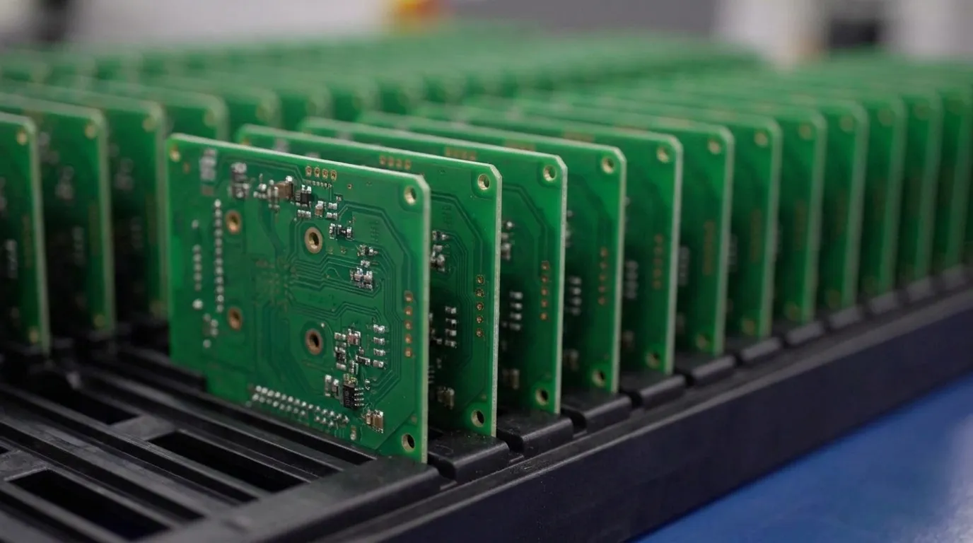
Key Takeaways for IPC Class 3 Programs
- IPC Class 3 represents the highest reliability classification for electronics where failure can be catastrophic and uptime is critical.
- IPC-6012F, IPC-A-610J and J-STD-001J define strict requirements for bare-board fabrication, solder-joint acceptance and soldering-process control that exceed Class 2 limits.
- Design-for-manufacturability decisions made during schematic and layout determine whether a board can meet Class 3 criteria without late redesign.
- Full lot traceability, material certificates, microsection reports and serialized inspection records are standard for defense, aerospace and medical programs.
- Pro-Active Engineering’s integrated U.S. workflow, from DFM review through final test, embeds Class 3 requirements from day one; discuss a high-reliability program with the team.
Where IPC Class 3 Reliability Standards Apply
IPC Class 3 applies to high-performance electronic products where continuous performance or performance on demand is critical and downtime is unacceptable. Aerospace avionics, military electronics, medical life-support systems and space electronics are primary application domains. Safety-critical industrial control systems and long-life infrastructure electronics also fall within this classification when failure carries severe consequences.
Early DFM decisions shape long-term reliability. Integrating DFM from the schematic phase, rather than at industrialization, avoids costly redesigns when targeting Class 3 requirements. Programs that defer DFM often encounter manufacturability issues, documentation gaps and compliance failures that compress schedules and increase lifecycle cost.
IPC-6012F Fabrication Criteria for Class 3 Boards
IPC-6012F, the current major revision of the qualification and performance specification for rigid printed boards, defines fabrication and acceptance requirements a bare board supplier must meet. These requirements cover conductor and dielectric integrity, hole wall plating, copper wrap, annular ring, registration, solder mask, cleanliness, electrical verification and coupon testing. The standard was released in October 2023.
Under Class 3, acceptance criteria for these attributes are the most stringent in the IPC-6010 family. Lifted or fractured annular rings are not permitted and plating voids in vias or holes must be absent. Annular ring integrity on both external and internal layers must be maintained with no breakout on any layer. Blind and buried vias must be filled or planarized to prevent flux trapping during assembly, which can cause laminate degradation or electrochemical migration over time.
These stringent fabrication requirements are met consistently only when design decisions account for them from the start. DFM guidance for Class 3 fabrication centers on several design choices made before a board reaches the fab house:
- Via design must reflect tight drill registration tolerances and aspect ratio limits that support reliable copper plating through the barrel.
- Material selection must favor laminates with thermal properties that resist delamination under repeated thermal stress.
- Registration control across all layers must appear explicitly on the drawing or purchase order, including the target IPC-6012 revision, performance class and any applicable addenda.
- Teardrop pads are recommended on all vias to reinforce the trace-to-pad junction against thermal cycling and mechanical stress.
- Via-in-pad fill and cap requirements, back-drill or blind and buried via specifications and solder mask dam constraints must be noted in fabrication notes early in design.
Buyers who specify the exact IPC-6012 revision, required performance class, any addenda, test coupon strategy and retained records on the drawing or purchase order reduce ambiguous quotations and post-delivery disputes.
IPC-A-610J and J-STD-001J Assembly Criteria for Class 3
IPC-A-610J is the current revision of the Acceptability of Electronic Assemblies standard and supersedes IPC-A-610H. It was released alongside IPC-J-STD-001J, which defines how soldering processes must be performed and controlled. Both standards were published in March 2024 and are cited together in professional RFQs for high-reliability programs.
Under IPC-A-610 Class 3, solder joint acceptance criteria are the most demanding in the standard, with tighter limits applied across every joint type. SMT chip component side overhang is limited to no more than 25% of the component termination area width (W) or 25% of the land width (P), whichever is less. Through-hole solder fill and other termination criteria are similarly tightened relative to Class 2. QFN and DFN side-wall fillet requirements follow the same pattern, and BGA voids in the core stress zone may be rejected even when total voiding remains within the general limit. Beyond dimensional criteria, any thermal-stress-induced measling or delamination is classified as a defect.
IPC-A-610J removed the “Target” condition category entirely, classifying conditions only as acceptable, process indicator or defect. This change reduces inspector-to-inspector variation and supports consistent visual acceptance judgments across Class 3 programs.
DFM considerations for Class 3 assembly focus on component behavior, footprint quality and process control:
- Component selection must support thermal profiles required for controlled, repeatable reflow without exceeding package ratings.
- Footprint design must enable solid solder fillet formation and inspection access for automated and human visual review.
- Thermal profile documentation and process control records must demonstrate consistent, repeatable soldering conditions across production lots.
- Component alignment must remain within maximum allowable rotation and overhang limits, with positional deviation rejected even when electrical function remains intact.
A credible Class 3 build requires certified operators and inspectors with a certified IPC trainer maintaining the program, documented process control and automated optical inspection plus X-ray for hidden joints such as BGAs.
Get a quote for Class 3 assembly on an upcoming program.
Inspection, Testing and Microsection Expectations for Class 3
IPC-A-610J supplies visual acceptance criteria for Class 3 assemblies but does not mandate a specific percentage or coverage rate of visual inspection, while Class 2 permits statistical sampling. This, combined with tighter acceptance criteria across solder joints, component placement and cleanliness, increases inspection time and operator involvement relative to Class 2 programs.
Class 3 programs require a layered inspection system that combines 3D solder paste inspection before reflow, 3D automated optical inspection after reflow, X-ray for BGA and QFN voiding and hidden bridging, and human visual adjudication for ambiguous edge cases. Automated methods support inspection but do not replace visual sign-off under Class 3.
Microsection analysis is performed as requested by the customer or, if unspecified, on a sampling basis determined by C=0 4.0 AQL according to production panel quantity. This analysis verifies via barrel plating thickness, annular ring dimensions and dielectric layer thickness. Metallographic cross-sectioning reveals voids or nodules at high magnification and confirms that plating meets both average and local minimum thickness requirements.
Electrical testing requirements for Class 3 programs include continuity and isolation verification across all nets. Functional testing validates circuit performance under representative operating conditions. Integrating these test steps within a single manufacturing workflow reduces the risk of escapes that occur when test is managed by a separate vendor with incomplete build history.
Traceability and Documentation for Class 3 Electronics
IPC Class 3 requires full traceability and more detailed manufacturing documentation than Class 2, including material batch tracking, process parameter logs, inspection reports for each production stage and operator and machine identification. Traceability means every step of the manufacturing process can be tracked and verified, which enables effective root cause analysis if a board fails in service.
Records that may be requested for Class 3 programs include:
- Certificate of conformity
- Material certificates and lot records
- Electrical test records
- Impedance reports
- Microsection reports
- First-article inspection reports
- AOI and X-ray records
- Lot traceability documentation
- Rework history tied to board serial number
A manufacturer may perform internal testing without automatically supplying the complete report package unless the customer states which records must be delivered. Serialization and traceability rules, material and test report requirements and repair restrictions should appear in the RFQ package.
IPC Class 2 Versus Class 3: Reliability and Documentation Shifts
Under IPC-A-610, Class 2 targets dedicated-service electronics that accept occasional cosmetic and solder imperfections within defined limits, while Class 3 targets high-reliability products that require stricter workmanship criteria with fewer concessions on solder fillets, heel coverage, voids and damage. Class 2 applies to products where extended service life is important but not critical. Class 3 covers products where high performance is required at all times and failure carries unacceptable risk.
Moving from Class 2 to Class 3 tightens acceptance criteria for solder fillet geometry, plated-through-hole fill, allowable component misalignment, voiding, cleanliness and plating, so conditions acceptable at Class 2 become rejectable defects at Class 3. Disturbed solder joints are treated as process indicators in Class 2 but as defects requiring rework in Class 3. Class 3 also requires thorough cleaning with residue levels below IPC-TM-650 limits, while Class 2 permits noncorrosive residues outside high-voltage areas.
The documentation burden also increases substantially. As products move from Class 2 to Class 3, standards become progressively more stringent with a more comprehensive audit trail required to demonstrate compliance. Inspection frequency increases, first-pass yield at AOI and final inspection is lower, and additional cross-sectioning and X-ray sampling are required. The unit cost difference between Class 2 and Class 3 can be substantial depending on complexity, driven by tighter process control, increased inspection time and higher documentation requirements.
Implementing Class 3 Requirements with an Integrated U.S. Partner
Pro-Active Engineering is a Wisconsin-based electronic design and manufacturing solutions provider with ISO 9001:2015, AS9100, ITAR, JCP and Nadcap credentials. The company operates a single integrated workflow that spans PCB design and DFM review, rapid prototyping, SMT and through-hole assembly, conformal coating, functional testing and box build. All services are consolidated under one roof, which reduces the communication gaps and accountability diffusion that occur when design, fabrication, assembly and test are managed by separate vendors.
For Class 3 programs, this integrated workflow addresses three recurring failure modes in regulated-industry supply chains:
- Prototype-to-production disconnect: Prototypes built on the same production processes and equipment used for volume runs ensure that assemblies passing Class 3 inspection in development scale into production without process drift.
- Documentation gaps: AS9100-aligned quality management systems generate the material certificates, inspection records, lot traceability and configuration control documentation that defense, aerospace and medical customers require at delivery.
- Vendor fragmentation: This consolidated structure reduces the number of handoffs where requirements can be lost, misinterpreted or incompletely transferred.
Pro-Active Engineering’s advanced interconnect capabilities, including wire bonding, flip chip assembly and hybrid high-density assemblies, support compact, high-performance designs common in aerospace and defense applications. Thermal management solutions, including silver sintering, direct thermal path technology and advanced metal-core constructions, address thermal demands that accompany Class 3 reliability requirements in high-power and harsh-environment applications.
ITAR registration and NIST 800-171 alignment support data-handling, access control and documentation practices required for controlled programs. JCP certification and Nadcap accreditation provide additional evidence of process discipline for customers in regulated sectors.
Share project details for a DFM review aligned to Class 3 requirements.
Conclusion: Building Confidence in Class 3 Programs
IPC Class 3 functions as a coordinated set of requirements spanning fabrication under IPC-6012F, assembly and inspection under IPC-A-610J, soldering process control under J-STD-001J and traceability practices aligned with AS9100. Each layer of the standard reinforces the others. Compliance depends on embedding these requirements in early design decisions rather than treating them as a final inspection filter.
Programs that engage an integrated domestic partner with the right certifications, process infrastructure and DFM capability from day one reduce the risk of late-stage failures, documentation gaps and prototype-to-production disconnects that create schedule and regulatory exposure in mission-critical work.
Pro-Active Engineering’s end-to-end workflow, domestic manufacturing footprint and certified quality management system are structured to support Class 3 programs from concept through production. Start the conversation about program requirements, DFM review and Class 3 compliance planning.
Frequently Asked Questions
What is the difference between IPC Class 2 and IPC Class 3 for PCB assembly?
IPC Class 2 applies to dedicated-service electronics where extended service life is important but occasional imperfections within defined limits are acceptable. IPC Class 3 applies to high-reliability products where continuous performance is required and failure carries unacceptable risk. Under IPC-A-610J, Class 3 tightens acceptance criteria across solder fillet geometry, through-hole fill, component placement, voiding, cleanliness and plating. Conditions that pass Class 2 inspection, such as disturbed solder joints or minor positional deviation, become rejectable defects under Class 3. The documentation burden also increases, with full lot traceability, material certificates, microsection reports and serialized inspection records required at delivery.
Which IPC standards govern Class 3 fabrication and assembly?
Three standards work together for Class 3 programs. IPC-6012F, released in October 2023, is the current qualification and performance specification for rigid printed boards and governs bare board fabrication requirements including conductor integrity, hole wall plating, annular ring, dielectric spacing and coupon testing. IPC-A-610J defines visual and dimensional acceptability criteria for finished PCB assemblies. J-STD-001J defines how soldering processes must be performed and controlled. High-reliability RFQs typically invoke all three at Class 3. IPC-A-600 governs bare board visual acceptability separately and should also be specified when fabrication class is a contract requirement.
What traceability documentation is required for IPC Class 3 PCBs in defense and aerospace programs?
IPC Class 3 programs in regulated industries require full lot traceability and detailed manufacturing documentation at every production stage. Records that customers may request include a certificate of conformity, material certificates with lot identification, electrical test records, impedance reports, microsection reports, first-article inspection reports, AOI and X-ray records, lot traceability documentation and rework history tied to individual board serial numbers. Serialization rules, material and test report requirements and repair restrictions should be specified in the RFQ package. A manufacturer may perform internal testing without automatically supplying the complete report package unless the customer explicitly states which records must be delivered with the product.
How does DFM affect IPC Class 3 compliance?
Design for manufacturability decisions made at the schematic and layout phase determine whether a board can be fabricated and assembled to Class 3 requirements without redesign. Common DFM issues that create Class 3 compliance risk include annular rings that are too small for the drill registration capability of the fab house, missing solder mask dams on fine-pitch components, via-in-pad designs without explicit fill and cap specifications and trace spacing that does not account for voltage clearance requirements. Integrating DFM review from the earliest design phase, rather than at the industrialization stage, avoids redesigns and late-stage compliance failures. An integrated manufacturing partner that operates design and production within a single workflow is positioned to identify and resolve these issues before they reach fabrication.
Why does Pro-Active Engineering’s integrated workflow reduce risk for Class 3 programs?
Vendor fragmentation is a common source of compliance risk in Class 3 programs. When design, fabrication, assembly, test and documentation are managed by separate vendors, requirements can be lost or misinterpreted at each handoff and accountability for failures becomes diffuse across the supply chain. Pro-Active Engineering consolidates design, rapid prototyping, PCB assembly, conformal coating, functional testing and box build into a single workflow under one roof. This structure ensures that Class 3 requirements established during DFM review carry through every production stage, that documentation is generated and retained within a single quality management system aligned to AS9100 and that one accountable partner owns the outcome from concept through delivery.