

Last updated: August 10, 2026
Key Takeaways for Aerospace PCB DFM
- DFM must remain active from schematic capture through flight-ready hardware for aerospace programs that require IPC Class 3, AS9100 and ITAR compliance.
- A seven-step aerospace DFM checklist covers IPC Class 3 conformance, AS9100 alignment, ITAR registration, HDI and rigid-flex stack-up, thermal and signal-integrity validation, traceability and counterfeit mitigation.
- Rigid-flex DFM in aerospace demands strict bend-radius control, tailored material selection and component placement rules that differ from standard PCB guidelines.
- An integrated US-based partner closes vendor hand-off gaps, reduces traceability risk and supports smooth transfer from production-built prototypes to volume manufacturing.
- Ready to consolidate an aerospace PCB workflow under one accountable partner? Start a technical review with Pro-Active Engineering.
Seven-Step PCB DFM Checklist for Aerospace Programs
This seven-step checklist reflects requirements aerospace programs encounter most often. Engineering managers can apply it to evaluate a prospective partner’s DFM process or to audit an existing design before fabrication.

- IPC Class 3 conformance review. Verify that annular rings, via drill sizing, drill position tolerances, copper plating minimums and dielectric spacing all meet IPC-6012 Class 3 high-reliability requirements. For space or avionics programs, confirm whether IPC-6012 FS (Flight Space) applies.
- AS9100 quality system alignment. Confirm the partner holds a current AS9100 certification and that DFM outputs, including design review records, nonconformance logs and change control documentation, are captured within that quality management system.
- ITAR registration and controlled-data handling. Validate that the partner is ITAR-registered with the DDTC and maintains documented access controls, personnel training records and data-handling procedures for controlled technical data.
- HDI and rigid-flex stack-up review. Confirm that microvia structures, sequential lamination sequences and controlled-impedance layer assignments are reviewed against IPC-2226 and IPC-6016 before fabrication release. For rigid-flex designs, verify IPC-2223 and IPC-6013 Class 3 compliance.
- Thermal and signal-integrity validation plan. Require a documented plan covering controlled-impedance coupon testing, TDR and VNA measurement correlation to simulation and thermal via placement review per IPC-2221B before production release.
- Full traceability and documentation chain. Confirm that approved stack-up records, material certifications, process records, microsection evidence and nonconformance records form a closed evidence chain traceable from approved design intent to the built and released product.
- Counterfeit component mitigation. Verify that the partner applies a documented counterfeit avoidance methodology. Pro-Active Engineering uses SAE AS5553B and performs BOM scrubbing for lifecycle risk and obsolescence using tools such as SiliconExpert.
Rigid-Flex DFM Rules for Aerospace Reliability
Rigid-flex PCBs in aerospace programs follow IPC-2223 for design and IPC-6013 Class 3 for qualification and performance. Rigid sections within the same assembly also fall under IPC-6012. J-STD-001 Class 3 high-reliability soldering requirements apply throughout.

Bend radius sets the reliability baseline for rigid-flex designs. IPC-2223 guidelines distinguish between static and dynamic flex applications, with dynamic applications requiring more generous bend radii to prevent copper cracking and dielectric failure. A minimum keep-out zone at the rigid-flex boundary and adequate coverlay pullback in flex zones help prevent delamination under vibration.
Material selection directly affects long-term performance. Aerospace rigid-flex designs typically use polyimide films for flex cores and rolled annealed copper for dynamic-flex layers, with adhesiveless constructions preferred for improved reliability. Stainless steel stiffeners suit high-vibration environments because they provide strong mechanical support.
Component placement rules protect flex regions from stress. SMT components must be placed on rigid or supported areas only. Dynamic bend zones must contain no components or vias. Copper planes in bend areas should use cross-hatched patterns rather than solid copper to reduce stress during flexing.
High-frequency rigid-flex designs require tight control of back-drilling depth and dielectric thickness between back-drilled layers. These controls depend on close coordination between the design team and the fabricator, which becomes structurally easier when both functions share a single workflow.
AS9100 PCB Manufacturing Partner Evaluation Framework
These technical DFM requirements highlight a broader need to confirm that a partner can deliver on them consistently. Program managers can use the following evaluation framework to assess PCB DFM and manufacturing partners. Each attribute maps to a practical consideration that can be verified during a supplier audit or technical review.

AS9100 certification confirms that the quality management system governs the full workflow. ITAR registration builds on that foundation by verifying active DDTC registration and documented access controls for controlled technical data. Nadcap accreditation adds a third layer of independent validation, focused on special processes such as soldering and coating.
Beyond certifications, DFM integration ensures manufacturability review occurs during the design phase rather than after layout completion, when changes cost more. That early review depends on traceability systems that support audit readiness through ERP-driven lot tracking from raw material through finished assembly. Counterfeit avoidance extends traceability upstream, following documented methodology aligned with SAE AS5553B and including BOM lifecycle scrubbing.
Prototype-to-production transfer reduces process risk by using full production processes for prototypes, so the process record transfers directly to volume manufacturing. Domestic manufacturing keeps fabrication and assembly within the United States to reduce geopolitical exposure and support ITAR compliance.
These attributes cluster around a central theme of integration. The framework favors partners that consolidate capabilities instead of spreading them across multiple vendors.
Why an Integrated US-Based Partner Reduces Program Risk
Fragmented vendor models separate design, fabrication, assembly, coating and test across multiple firms. Each vendor boundary creates a potential gap in traceability, a point of file loss and a source of schedule uncertainty. An integrated partner removes many of those gaps by design. When the engineers who review the DFM also oversee the prototype build and the production transfer, manufacturability issues surface during design when they cost less to resolve.
Domestic manufacturing adds a second layer of risk reduction beyond process integration. Pro-Active Engineering operates from a single facility in Sun Prairie, Wisconsin, where PCB design, rapid prototyping, assembly, conformal coating and system integration share one quality management system, one ERP-driven traceability chain and one engineering team.

Ready to consolidate design and production under one accountable partner? Connect with our team and Pro-Active Engineering’s engineers will map requirements to capabilities.
Frequently Asked Questions for Aerospace PCB DFM
What certifications should an aerospace PCB DFM partner hold?
An aerospace PCB partner should hold AS9100 certification covering the full scope of services, including design, fabrication and assembly, along with ITAR registration with the DDTC. Nadcap accreditation for relevant special processes provides additional independent validation. IPC-A-610 Class 3 workmanship standards and J-STD-001 Class 3 soldering requirements should be standard practice.
For programs involving controlled technical data, NIST 800-171 alignment and CMMC readiness are increasingly expected. Pro-Active Engineering holds AS9100, ITAR registration, Nadcap accreditation, JCP certification and ISO 9001:2015, and maintains alignment with NIST 800-171 and CMMC readiness requirements.
How does an integrated DFM workflow reduce total cost of ownership for aerospace programs?
DFM embedded in the design phase resolves manufacturability issues before they generate rework, scrap or schedule delays. A single partner managing design through production also removes vendor management overhead, reduces the risk of file loss or miscommunication at hand-off points and preserves a continuous process record from prototyping through production.
These structural efficiencies reduce lifecycle cost even when the per-unit price of an integrated domestic partner exceeds that of an offshore or fragmented alternative.
Can a single partner handle both rapid prototyping and full production for low-to-mid volume aerospace programs?
Pro-Active Engineering’s Speed Shop delivers production-ready prototypes with a minimum order quantity of one unit, built using the same SMT and through-hole processes as full production runs. That process continuity means the prototype build record, including reflow profiles, SMT parameters and inspection results, transfers directly to volume manufacturing without re-qualification.
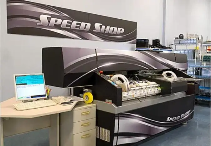
The same engineering team supports both phases, so no prototype-to-production disconnect occurs. Pro-Active serves low-to-mid volume, high-complexity aerospace programs and scales capacity as program needs grow.
How does rigid-flex DFM differ from standard PCB DFM in aerospace applications?
Rigid-flex DFM introduces additional design rules that do not apply to all-rigid boards. Bend radius must be specified and validated against IPC-2223 requirements for static or dynamic flex applications. Component placement is restricted to rigid or supported areas only, with no components or vias in dynamic bend zones.
Material selection, including flex core material and copper type, must match the mechanical and thermal demands of the application. Coverlay design, stiffener placement and the rigid-flex boundary keep-out zone all require explicit DFM review. These rules must be enforced during design, not discovered during fabrication, so rigid-flex programs benefit most from a partner whose design and manufacturing teams share a single workflow.
What does onboarding look like when transitioning an existing aerospace program to a new PCB partner?
Pro-Active Engineering’s onboarding process is structured to minimize disruption. Programs typically begin with a pilot build, either a prototype or a small production run, that demonstrates process capability and documentation quality before full production transfers.
The engineering team conducts a DFM review of existing designs, identifies any manufacturability or compliance gaps and documents findings in a format compatible with the program’s quality management requirements. Traceability records, test programs and process documentation are established during the pilot and carry forward into volume production. Many aerospace customers start with a single board type and expand the relationship across their program portfolio as confidence builds.
Next Steps: Moving from Requirements to Technical Review
Selecting a PCB DFM partner for a complex aerospace program follows a structured sequence. Moving through each step systematically reduces the risk of selecting a partner whose capabilities do not match the program’s actual requirements.
- Map internal requirements. Document the program’s IPC class requirements, applicable certifications, ITAR status, layer count, technology type (rigid, HDI, rigid-flex), volume profile and schedule constraints before approaching any supplier.
- Build a short list using the evaluation framework. Apply the AS9100 partner evaluation framework above to filter candidates. Remove any partner that cannot demonstrate current AS9100 certification, ITAR registration and a documented DFM process integrated into the design phase.
- Request a technical review. Share design files, stack-up requirements and program constraints with short-listed partners. Evaluate the depth and specificity of the DFM feedback. A credible partner identifies specific manufacturability risks, not just confirms that the design passes basic rule checks.
- Assess traceability and documentation capability. Ask for examples of the partner’s traceability records, nonconformance documentation and first article inspection reports. Verify that these outputs meet the program’s audit and compliance requirements.
- Run a pilot build. Commission a prototype or small production run using full production processes. Evaluate turnaround, documentation quality and the fidelity of the process record before committing full production volume.
Pro-Active Engineering supports aerospace and defense customers through every step of this process, from initial requirements mapping through production and system integration. The engineering team remains available for technical reviews, DFM consultations and capability discussions at any stage of program development.
Begin a technical review of program requirements with Pro-Active Engineering’s aerospace team.