
Last updated: August 22, 2026
Key Takeaways for PCB DFM Decisions in 2026
- PCB design teams in 2026 can choose among three DFM delivery models: CAD-native tools, standalone or cloud platforms, and manufacturer-provided workflows that embed DFM from day one.
- CAD-native and standalone DFM tools validate against rules or published capabilities, but they cannot match checks tied to the exact production process in use.
- Manufacturer-provided DFM reduces handoff friction by bringing fabrication and assembly knowledge into the design phase, which cuts costly late-stage changes.
- Pro-Active Engineering consolidates DFM, prototyping, assembly and compliance under one ITAR-registered domestic partner, which lowers total cost of ownership and risk for defense, aerospace, medical and industrial programs.
- Teams ready to reduce risk and eliminate extra tools can start a pilot or production program with Pro-Active Engineering.
Three DFM Delivery Models for Modern PCB Workflows
Each DFM delivery model supports a different stage in the design-to-production handoff. CAD-native checkers run inside the layout tool and catch issues early. Standalone and cloud platforms analyze Gerber or ODB++ outputs against a manufacturer process window. Manufacturer-provided DFM embeds fabrication and assembly knowledge directly into the engineering relationship and closes the handoff gap.
The right model depends on where manufacturability risk enters the program and who holds accountability for resolving it. That accountability question leads directly to what standard design rule checks miss and why DFM analysis catches failures that DRC cannot.
What DFM Catches That CAD DRC Misses
Design rule checks verify the rules that were encoded. They do not confirm alignment with the selected stackup, the target manufacturer process window, the assembly profile or the operating environment.
Advanced DFM analysis operates against factory physics, not only user-defined numeric limits. The following seven categories represent the most common manufacturability failures that pass DRC but cause production problems and highlight the gap between geometric compliance and process reliability.
- Acid traps: Acute-angle trace junctions trap residual etching chemistry, which causes localized over-etching and open circuits. DRC passes the geometry when spacing and width rules are met.
- Copper slivers: Narrow isolated copper features can peel during fabrication and create intermittent shorts. Standard DRC does not flag these isolated geometries.
- Solder mask slivers: Dams thinner than the manufacturer minimum between fine-pitch pads allow solder bridging during reflow, which sits outside the scope of electrical DRC.
- Annular ring and drill-to-copper violations: Drilling misalignment and plating variation can break layer connections on rings that satisfy CAD minimums but fall short of real process tolerances.
- Via-in-pad risks: Unplated or unplugged vias under component pads cause solder wicking into the barrel during reflow, which produces dry joints that DRC does not address.
- Thermal mass imbalance: Uneven copper connections on opposing SMD pads create tombstoning risk during reflow, a manufacturability condition invisible to electrical rule checks.
- Board edge clearance: Components and traces placed too close to V-score lines or routed board edges sustain mechanical damage during depaneling, a risk DRC does not evaluate.
DFM also evaluates panelization strategy, fiducial placement, component orientation for pick-and-place efficiency and silkscreen overlap with pads or vias. These checks address manufacturing concerns that sit entirely outside standard DRC scope.
Comparing Altium DFM Checker and Standalone Platforms
Altium Designer includes an integrated CAM environment as part of the standard installation, which enables direct inspection of Gerber, drill and IPC outputs inside the same tool used for layout. This arrangement reduces file translation overhead and keeps DFM feedback close to the design phase.
Altium technical marketing notes that DFM tools cannot replace design rules found in PCB design software, and smart designers use both. The CAD-native checker validates against rules the designer configured. It does not validate against the specific process window of the manufacturer that receives the files.
Standalone tools address that gap by running checks against a manufacturer published capabilities on the exported manufacturing package. Tradeoffs for Altium users include the following factors.
- Setup effort: Standalone platforms require a separate installation or cloud account, file export from Altium and rule mapping to a specific fab capabilities before the first check runs.
- Rule-mapping depth: Cloud platforms such as JLCDFM check across copper, solder mask, drilling, silkscreen and assembly modules against that manufacturer process, which provides deeper process-specific coverage than a generic in-CAD ruleset.
- Handoff friction: Every standalone tool adds a file export, a login, a separate report and a manual reconciliation step before the design reaches the contract manufacturer. That friction compounds across revision cycles.
A complete manufacturing submission requires Gerber or ODB++, NC drill files, fabrication drawing, stackup, material and copper requirements, controlled-impedance notes, netlist data, quantity, surface finish, test requirements and target delivery, plus BOM, CPL, assembly drawings and test instructions when assembly is included. Standalone DFM tools still require that handoff and only check the files before they cross it.
When Manufacturer DFM Replaces Extra Software
Manufacturer-provided DFM removes the handoff by embedding fabrication and assembly knowledge into the engineering relationship before layout freezes. Treating DFM as an integral part of the design process rather than a late-stage check reduces prototype-to-production disconnects. Stackup choices, via structures and feature density align with real factory capabilities from the start.

Engaging EMS partners during the DFM phase reduces manufacturing delays and material sourcing issues during NPI cycles. That engagement becomes practical when the manufacturer participates in the design conversation instead of receiving completed files at the end.
Pro-Active Engineering operates as that partner. DFM enters the design phase, not only the period after Gerber export. The engineering and manufacturing teams share one workflow, so sourcing insight, quality planning and process constraints inform layout decisions before they become costly changes. Programs see fewer redesigns, predictable production transfer and a single accountable partner from schematic through shipment.
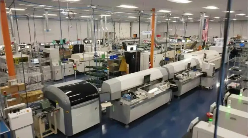
For programs in defense, aerospace, medical and industrial sectors, that accountability carries additional weight because regulatory compliance directly affects manufacturability decisions. Pro-Active Engineering holds ISO 9001:2015, AS9100, ITAR registration, JCP certification and Nadcap accreditation. These certifications require compliance documentation, traceability and controlled processes to sit inside the standard workflow rather than appear as add-ons.

Total cost of ownership for disconnected product development workflows extends beyond license fees. It includes implementation, training, IT infrastructure, vendor management, file management overhead and rework costs from revision errors. Consolidating DFM, prototyping, assembly and compliance under one partner reduces that cost by eliminating rework, minimizing downtime and simplifying vendor management.
CAD-Specific DFM Choices for Altium, KiCad and Cadence
The three DFM delivery models interact differently with each major CAD environment. Clear insight into setup effort, rule-mapping depth and handoff friction for each combination helps engineering teams select the lowest-risk path.
Altium Designer users start with the most integrated CAD-native DFM option. The built-in CAM environment reduces file translation overhead and rule-mapping within the tool remains straightforward for teams fluent in Altium constraint manager. Standalone cloud tools add process-specific depth but require a separate export and reconciliation workflow. Manufacturer-provided DFM removes both the export step and the rule-mapping burden and replaces them with direct engineering collaboration against the production process.
KiCad users face higher setup effort with standalone tools because KiCad native DRC offers less configuration flexibility than many commercial alternatives and rule export formats vary by version. Cloud platforms that accept Gerber inputs work with KiCad outputs, but rule mapping to a specific manufacturer process window still requires manual configuration. Manufacturer-provided DFM becomes particularly valuable for KiCad-based programs because it replaces a fragmented, manually configured check chain with a single engineering relationship that owns process accuracy.
Cadence Allegro environments, common in high-reliability and high-speed design programs, provide deep constraint management but require significant setup effort to align internal rules with a specific manufacturer process. Cadence Allegro X AI offers generative assistance for placement and routing, but the engineer still verifies constraint accuracy, routing quality, signoff analyses and release data. Standalone DFM tools add another verification layer with separate setup and licensing overhead. For Cadence users on high-reliability programs, manufacturer-provided DFM that integrates sourcing insight and quality planning from day one reduces the risk that a technically correct layout fails against specific fab process limits.
Across all three environments, the manufacturer-provided model reduces setup effort to near zero, delivers rule-mapping depth tied to actual production processes and removes handoff friction by making the manufacturer a participant in the design phase rather than a recipient of completed files.
Frequently Asked Questions About Manufacturer-Provided DFM
Design Control When Working With a Manufacturer DFM Team
Pro-Active Engineering operates as an extension of the in-house team, while engineers retain full ownership of the design. The manufacturer role centers on surfacing process constraints, sourcing risks and quality considerations early enough to influence layout decisions before they become expensive changes. Regular design reviews and transparent reporting keep the engineering team in control throughout the program.
Onboarding From Standalone DFM to a Manufacturer Workflow
Pro-Active Engineering onboarding process minimizes disruption. Programs can start with a pilot build to validate the workflow before shifting full production. The engineering team reviews existing design files, identifies manufacturability concerns and aligns on process requirements before the first build. Many customers report immediate improvements in communication and turnaround from the first engagement.
Scaling Manufacturer DFM From Prototype to Volume
Pro-Active Engineering uses the same production processes for rapid prototypes and volume builds. DFM decisions made during the prototype phase carry directly into production without revalidation. The workflow scales from single-unit R&D builds through low-to-mid volume production runs without a new DFM tool, a new vendor relationship or a new set of design rules.
Accuracy Advantages Over Cloud-Based Standalone Tools
Cloud-based standalone tools check designs against a manufacturer published process capabilities. Manufacturer-provided DFM checks designs against the actual process used to build the board, including sourcing constraints, assembly equipment capabilities, inspection criteria and quality standards. That alignment removes the gap between what a tool reports as acceptable and what the production floor can build reliably.
Suitability for ITAR-Controlled Programs
Cloud-based DFM tools require uploading design files to external servers, which creates data-handling risk for ITAR-controlled programs. Pro-Active Engineering is ITAR-registered and applies access controls, data-handling procedures, documentation practices and personnel training consistent with DDTC requirements. Design data remains within a controlled domestic environment throughout the engineering and manufacturing workflow.

Conclusion: A DFM Path That Reduces Risk and Extra Tools
Product complexity continues to rise at an unprecedented pace, driven by advanced processors, high-speed interfaces, dense power delivery networks and signal integrity demands that place growing pressure on PCB design teams. Adding more DFM tools into that environment increases cost and complexity without solving the fundamental prototype-to-production disconnect.
Pro-Active Engineering consolidates design, DFM, rapid prototyping, assembly, compliance and quality control under one domestic ITAR-registered roof. When engineering and manufacturing operate in the same workflow, as in the manufacturer-provided model, manufacturability, sourcing insight and quality planning enter the design phase before layout decisions lock. That consolidation, the single-partner model described earlier, delivers fewer surprises, fewer vendors and lower total lifecycle cost when engineering and manufacturing share one workflow.
Teams can start with a prototype or bring a full production program. In both cases, the workflow remains consistent and the accountability stays singular. Get started with Pro-Active Engineering.