
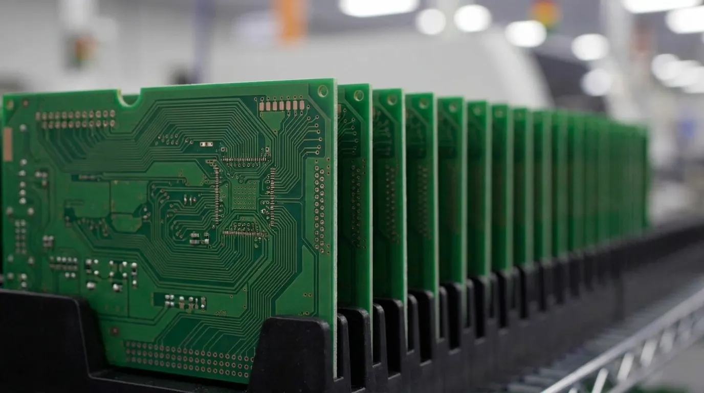
Key HDI Microvia Rules for Reliable ITAR Builds
- IPC-2226 defines microvias with a 1:1 maximum aspect ratio and 0.25 mm depth limit, which anchors reliable HDI PCB production.
- Aspect ratios between 0.75:1 and 0.8:1 improve plating uniformity, reduce voids and support stable signal performance in mission-critical designs.
- Stacked microvias work best when limited to two layers. Staggered configurations reduce thermal stress and failure risk for taller structures.
- Via-in-pad structures need resin fill, copper capping and controlled annular rings to support dependable fine-pitch BGA connections.
- Pro-Active Engineering builds these HDI microvia rules into every ITAR program. Discuss an HDI microvia build with the engineering team.
Microvia Aspect Ratio Limits That Protect Reliability
Aspect ratio, defined as microvia depth divided by finished diameter, sets plating behavior at the via bottom. It is the most critical HDI microvia constraint because it controls how copper deposits and how the structure survives thermal cycling.
IPC-T-50M sets a 1:1 maximum aspect ratio, but operating at that limit leaves no margin for manufacturing variation. A target range between 0.75:1 and 0.8:1 keeps designs inside the standard while reducing plating voids and crack initiation during reflow. Ratios below 0.8:1 also limit resistance spikes that can degrade signal integrity in dense HDI networks.
The aspect ratio formula is simple: AR = depth divided by finished diameter. Enter the finished diameter and dielectric thickness into this formula before locking a stackup in Altium or Cadence, because these values drive both manufacturability and reliability.
HDI Stackup Types and Layer-Build Decisions
IPC-2226 classifies HDI constructions into three primary types that guide stackup planning. Type I uses a single microvia layer on one or both sides of a core with plated through-holes. Type II adds buried vias to that structure to support more complex interconnects. Type III supports at least two microvia layers on one or both sides, which enables stacked or staggered configurations for the highest routing density.
Dielectric thickness between the surface layer and the reference pad directly sets the aspect ratio for each microvia. A dielectric range of 60–80 µm for L1–L2 microvias supports reliable laser-drilled formation at the recommended aspect ratios. Thinner dielectrics increase aspect ratio margin, while material selection must also consider glass weave uniformity, Z-axis CTE and copper surface roughness to maintain registration through sequential lamination.
Line and space rules tighten with each build-up layer as density increases. Advanced HDI fabrication supports trace and space down to 3/3 mil or finer. Sequential build-up lamination accumulates registration error, so early decisions on layer count and feature alignment strongly influence final yield and rework rates.
Stacked and Staggered Microvias in High-Reliability Designs
Stacked microvias align vertically across consecutive layers and form a continuous copper column. Staggered microvias offset horizontally between layers and spread Z-axis stress across a broader region. The selection between stacked and staggered structures drives reliability outcomes more than routing convenience.
Glass epoxy laminate expands at about 200 ppm/°C in the Z-axis, while copper expands at about 16 ppm/°C. Stacked columns concentrate this mismatch at a single interface, which becomes the weakest point in the structure. Staggered microvias distribute loads horizontally and vertically across offset layers, which slows fatigue accumulation over many thermal cycles.
Observed failure modes in stacked configurations include:
- Interfacial separation: the bond between two stacked vias fractures under repeated thermal excursion
- Barrel and corner cracks: crack propagation between capture and target pads during reflow
- Target pad pull-out: pad separation from the laminate surface under Z-axis stress
- Resin recession: dielectric pullback from the via barrel that reduces effective plating contact area
- Weak Microvia Interface (WMI): latent fractures in three-level stacks that self-heal below Tg and pass room-temperature continuity tests
Stacked microvia structures perform best when limited to two layers. When a third layer is required, a staggered configuration reduces WMI risk and improves long-term reliability. Maintain a vertical offset greater than the via diameter and at least 2 mil spacing between staggered structures. Aerospace and defense programs also require D-coupon thermal testing per IPC TM-650 before accepting stacked HDI designs.
Via-in-Pad Rules for Fine-Pitch BGA Reliability
Via-in-pad places a microvia directly beneath a component pad and supports escape routing under fine-pitch BGAs at 0.5 mm pitch and below. This structure enables dense fan-out, but it also creates a direct path for solder to wick into the via barrel during reflow. Without proper fill and cap, that wicking produces solder-starved joints and intermittent connections.
Production-ready via-in-pad specifications include:
- Fill with non-conductive or conductive resin to eliminate the internal void
- Cap with electroplated copper to create a flat, solderable surface
- Maintain a minimum 2 mil annular ring for laser-drilled microvias
- Size capture pads at drill diameter plus 0.006 inches as a baseline for advanced HDI builds
- Specify fill requirements explicitly in fabrication notes rather than relying on fabrication defaults
Teardrop annular rings further strengthen these pads by adding copper where traces neck into the via. This geometry improves structural integrity for traces narrower than 20 mils and increases resistance to shear forces in high-vibration environments.
Dielectric Thickness and Material Choices for Microvias
Dielectric thickness between microvia layers acts as an active design parameter, not a background dimension. It sets the aspect ratio, influences impedance and determines whether the laser can form a clean, consistent via barrel.
A dielectric thickness of 60–80 µm between the surface layer and the reference pad supports reliable microvia formation at standard diameters. Advanced HDI builds may use thinner dielectrics to tighten impedance control and increase interplane capacitance, which supports high-speed signaling.
Several material properties also shape microvia reliability:
- Glass weave uniformity: non-uniform weave creates registration drift across sequential lamination cycles
- Z-axis CTE: lower values reduce interfacial stress during thermal cycling
- Tg value: higher Tg laminates maintain dimensional stability at reflow temperatures
- Copper foil surface roughness: smoother or reverse-treated foils improve adhesion and impedance consistency at fine geometries
For aerospace, defense and medical HDI applications, IPC-4101 guides laminate selection alongside IPC-6012 Class 3 workmanship requirements. These standards align material performance with the reliability targets of regulated programs.
DFM Checklist for ITAR-Regulated HDI Programs
Generic HDI rules applied without manufacturing context create compliance exposure because they ignore documentation and traceability requirements. The following checkpoints connect each design rule to a production-transfer requirement for ITAR-regulated programs.
- Confirm aspect ratio at or below 0.8:1 for all microvia layers before releasing to fabrication
- Limit stacked microvia columns to two layers and document any exception with thermal test data
- Specify via fill type and copper cap requirements in fabrication notes
- Include separate laser drill files, impedance tables and full stackup notes in the fabrication data package
- Require D-coupon thermal testing per IPC TM-650 2.6.27A for any stacked configuration
- Apply IPC-6012 Class 3 workmanship requirements across all HDI layers
- Verify annular ring minimums in CAM using drilled hole size, not finished hole size
- Confirm dielectric thickness supports the target aspect ratio before the stackup is locked
- Run DRC and DFM checks during layout rather than after design freeze
- Maintain full traceability documentation from design revision through production lot
Pro-Active Engineering builds these checkpoints into the design phase so DFM runs in parallel with layout. This concurrent approach prevents late-stage redesigns on ITAR programs and keeps documentation aligned with the final build.
Start a DFM review with Pro-Active Engineering’s engineering team.
Ready-to-Use HDI Microvia Constraint Set
These constraints are formatted for direct entry into Altium or Cadence design rules. Each value aligns with IPC standards or established HDI fabrication guidance.
- Microvia aspect ratio (target): 0.75:1 to 0.8:1
- Microvia aspect ratio (maximum): 1:1 per IPC-T-50M
- Maximum microvia depth: 0.25 mm per IPC-T-50M / IPC-6012
- Typical finished microvia diameter: 80 to 100 micrometers
- Dielectric thickness (L1 to L2): 60 to 80 micrometers
- Maximum stacked microvia layers: 2, with staggered structures for three or more layers
- Staggered via offset: greater than via diameter with at least 2 mil spacing
- Minimum annular ring (laser-drilled): 2 mil
- Via-in-pad fill: resin fill plus copper cap for fine-pitch BGA escape routing
- Workmanship standard: IPC-6012 Class 3 for aerospace and defense programs
- Aspect ratio formula: AR = depth divided by finished diameter
Pro-Active Engineering applies these constraints inside an integrated engineering-to-manufacturing workflow where design and fabrication teams share one facility. This integration means designs enter production with DFM resolved, stackups validated and documentation traceable from first prototype through volume build. The single-site model removes vendor handoffs that often create compliance gaps in multi-supplier HDI programs.
Connect with Pro-Active Engineering’s HDI team to discuss the next build.
Frequently Asked Questions
How do stacked and staggered microvias compare for defense applications?
Stacked microvias align vertically across consecutive HDI layers and form a continuous copper column. Staggered microvias offset horizontally between layers and distribute Z-axis thermal stress across a wider area. In defense and aerospace applications, staggered configurations are preferred because they reduce interfacial separation risk during thermal cycling. Stacked configurations remain acceptable for one-to-two layer spans when routing density demands that structure, but they require D-coupon thermal testing per IPC TM-650 and should remain limited to two stacked layers. Three-level stacks introduce Weak Microvia Interface defects that can pass room-temperature continuity tests while harboring latent fractures that later fail in the field.
How does Pro-Active Engineering apply HDI microvia rules to ITAR programs?
Pro-Active Engineering integrates DFM into the design phase rather than treating it as a post-layout review. For ITAR programs, that approach brings aspect ratio validation, stackup confirmation, via fill specification and thermal test planning into the process before design freeze. The company holds ISO 9001:2015, AS9100, ITAR registration, JCP certification and Nadcap accreditation, which supports the documentation and traceability structure that regulated programs require. All engineering and manufacturing operations run under one roof in Sun Prairie, Wisconsin, which removes vendor handoffs that often create compliance gaps in multi-supplier HDI programs.
What causes microvia failures during thermal cycling, and how can design rules reduce them?
Microvia failures during thermal cycling arise from CTE mismatch between copper and the surrounding organic dielectric. The dielectric expands at a higher rate in the Z-axis than copper and generates shear stress at the capture-to-target pad interface. Common failure modes include interfacial separation, barrel cracks, corner cracks, target pad pull-out and resin recession. These failures often remain latent because they develop over hundreds of thermal cycles and may not appear in room-temperature continuity testing. Maintaining aspect ratios at or below 0.8:1, limiting stacked columns to two layers, specifying resin fill and copper cap for via-in-pad structures and requiring IPC TM-650 D-coupon testing all reduce failure probability in high-reliability builds.
What fabrication data does an HDI PCB need for production transfer?
A complete HDI fabrication package includes Gerber or ODB++ files, separate laser drill files distinct from mechanical drill files and a full stackup drawing with dielectric thickness and material callouts. It also includes impedance tables with target values and tolerances, via fill and cap specifications in the fabrication notes and an IPC-6012 Class 3 workmanship callout for defense and aerospace builds. Incomplete packages often cause prototype-to-production disconnects. Pro-Active Engineering reviews fabrication data as part of the DFM process to confirm that the package is complete before any board enters production.
Can Pro-Active Engineering support both HDI prototypes and full production runs?
Pro-Active Engineering manages the full program lifecycle from initial HDI layout through high-volume production. The Speed Shop delivers rapid-turn prototypes built with the same processes as production builds so designs validated at prototype scale transfer to volume manufacturing without process changes. This continuity matters for HDI programs where stackup, via fill and laminate selection must remain consistent across lots to maintain reliability and traceability. Engineering, assembly, testing, conformal coating and system integration all operate under one roof, which gives program managers a single accountable partner from first article through production delivery.