
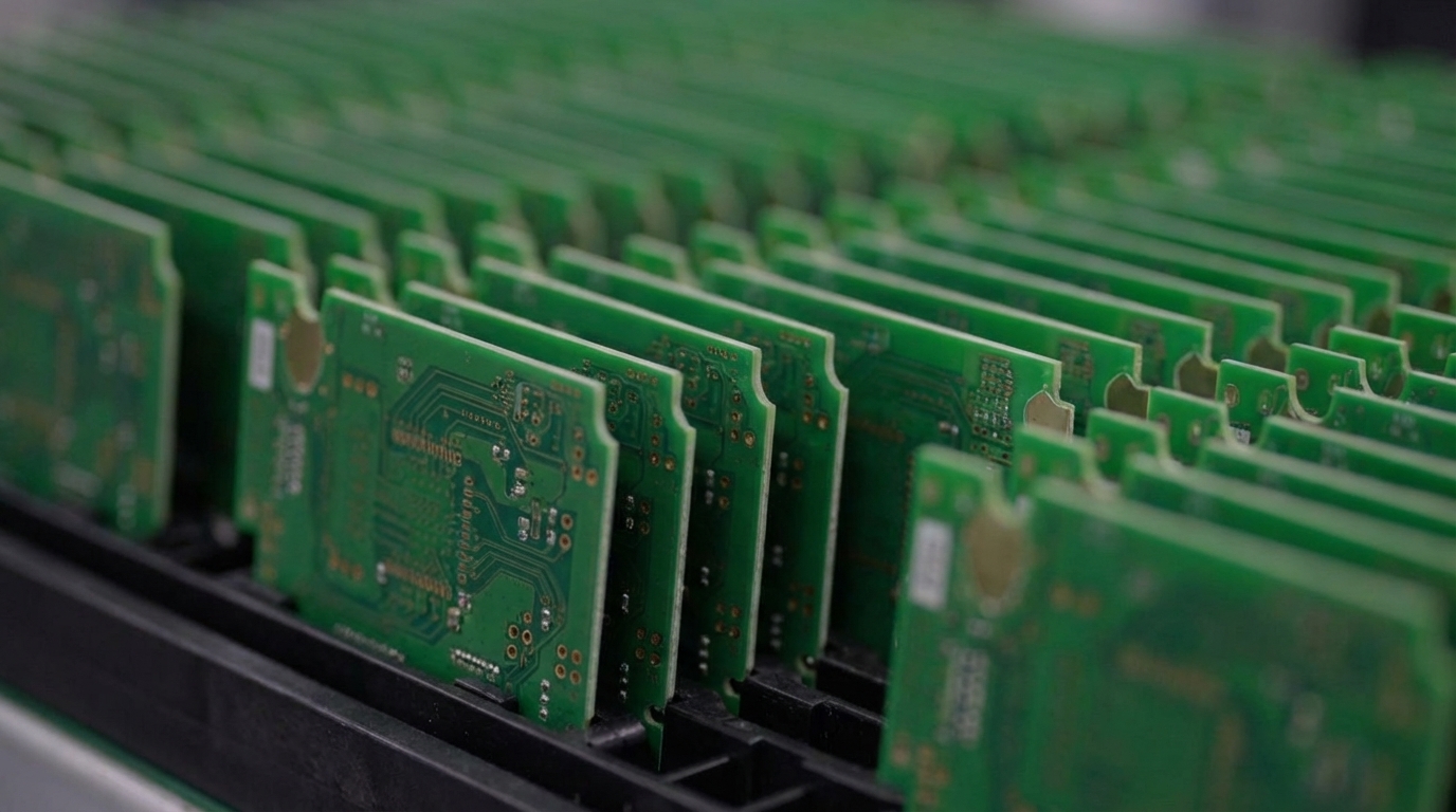
Last updated: August 25, 2026
Key Takeaways for High-Reliability Panelization
- Routed tabs with tooling rails and controlled router depanelization provide the most reliable panelization approach for aerospace, defense and medical prototypes, avoiding the board flex that V-scoring introduces.
- MLCCs must be oriented parallel to break lines with generous keep-out zones to prevent latent cracking that passes initial testing but fails in the field.
- Tooling rails sized to conveyor requirements with asymmetric L-pattern fiducials and local fiducials near BGAs support accurate SMT alignment and prevent assembly errors.
- Router depanelization is required for irregular board shapes, components near edges or IPC-A-610 Class 3 programs, while V-scoring is acceptable only for simple rectangular boards without edge components.
- Documenting the depanelization method on every drawing and engaging Pro-Active Engineering’s DFM team early supports production-ready panelization from prototype through volume manufacturing, and starts a DFM-driven panelization review.
Protecting MLCCs Near Break Lines
Multilayer ceramic capacitors are among the most vulnerable components in any panel array. Board bending during separation transfers tensile strain directly into MLCC bodies and solder joints, and the damage rarely appears in automated optical inspection results.
Ceramic capacitors that sustain internal cracks from depaneling stress can pass initial electrical and functional testing yet later develop open or short circuits during field operation under vibration or temperature change. That latent failure mode remains unacceptable in regulated programs.
Orientation provides the first line of defense. Large MLCCs in Class 2 dielectrics should be aligned parallel to the PCB edge or break-away tabs rather than perpendicular, which reduces mechanical stress during depanelization.
Keep-out distance matters as much as orientation. Any heavy, tall or brittle component within a few millimeters of a separation feature warrants review before panel release. Large MLCC packages should avoid placement near depanelization routes, PCB edge connectors and mounting holes because ceramic bodies can crack from PCB flexure during handling or separation. Where layout constraints force proximity to a break line, soft-termination MLCCs or polymer capacitors provide the recommended substitutes.
Tab placement must avoid twisting a thin board section or loading a nearby component, which concentrates stress on fragile parts during separation. Reviewing component distance from the score line and the bending direction with the manufacturer before release remains a required step, not an optional one.

For aerospace and defense programs, keep-out zones should exceed the minimums published for commercial assemblies. A generous buffer between any MLCC and a separation feature provides a low-cost reliability investment at the design stage. Have Pro-Active’s DFM team review MLCC placement before panel release.

Once component placement and keep-out zones are established, the panel itself must support accurate SMT assembly and controlled handling.
Designing Tooling Rails and Fiducials for Accurate Assembly
Tooling rails give conveyors a clamping surface free of components and carry the fiducials that SMT vision systems use to correct for panel distortion. Both functions fail when rails are undersized or fiducials are placed incorrectly.
Tooling rail width is sized to conveyor requirements, with tooling holes added on both sides for electrical testing fixture positioning. Automated conveyor systems require a clear keep-out zone along the top and bottom edge boundaries of the panel so that components, traces, test points or copper features are not crushed or shorted by conveyor chains.
Fiducial placement follows a non-symmetrical L-pattern. Three asymmetric global fiducials placed in an L-shape, at lower-left, upper-left and upper-right, enable accurate board alignment, rotation compensation and scale adjustment while preventing 180-degree orientation confusion that symmetric four-corner layouts can cause.
HDI sequential lamination and copper density variation can cause the absolute position of a fine-pitch BGA relative to the board outline to drift from CAD data, which requires local fiducials placed close to the package edge to provide a fresh optical zero after reflow. For every BGA or high-density SMT island above a threshold size, a pair of local fiducials should sit outside the package outline and clear of any copper or via.
Panel fiducials must be kept away from panel edges or V-scoring lines to prevent clamp interference during assembly and damage during depanelization. A copper-free zone around every fiducial prevents solder-mask registration errors from partially covering the mark and causing the SMT camera to see an incomplete circle or irregular edge.
For double-sided assemblies, identical panel fiducials must appear on both sides and be aligned vertically to support through-panel registration. Surface finish on fiducials should provide consistent reflectivity without oxidation. ENIG provides the preferred choice for high-reliability programs.
Choosing Router Depanelization Instead of V-Score
Router depanelization supports high-reliability prototypes more effectively than V-score in most regulated programs. V-score remains a fast, low-cost method for rectangular boards with no components near the edge, but it introduces higher mechanical stress.
V-score cuts must be perfectly straight lines that run edge-to-edge on the panel and cannot turn corners or follow curved board outlines. V-scoring is suitable only for straight-line separation, while tab routing supports any shape including curves and notches with tighter edge accuracy.
The stress argument carries equal weight. Depaneling stress commonly introduces latent damage including micro-cracks in solder joints, pad lifting, internal PCB damage and ESD breakdown, and these defects typically remain undetected by AOI, ICT or SMT yield checks and manifest later during drop testing, thermal cycling or long-term field operation.
Real-world production cases show that switching from high-stress depaneling methods to low-stress online milling can reduce failure rates substantially. That data point justifies the additional process planning that router depanelization requires.
Tab routing with mouse-bite perforations is the correct choice when:
- Boards have irregular or non-rectangular outlines, or components extend to or overhang the edge
- Components are placed close to the board edge, which rules out the bending force that V-scoring applies
- Multiple different board shapes must be combined in one panel
- IPC-A-610 Class 3 workmanship standards govern the program
V-score remains acceptable when all boards in the array are rectangular, share an identical outline and carry no components near the separation line. Outside those conditions, router depanelization provides the lower-risk path. Choosing the right method represents only half the task, and the decision must appear in fabrication and assembly drawings so the manufacturer executes it correctly.
Capturing Depanelization Method on Drawings
The depanelization method forms part of the reliability plan and must appear on fabrication and assembly drawings. Panel drawings must clearly define V-score lines, routed slots and tabs, and keep components, copper, vias and fragile features away from separation zones according to supplier rules.
Required callouts on a high-reliability panel drawing work together to control stress, geometry and inspection. These callouts include:
- Depanelization method, router, V-score or laser, with tool path or score-line location
- Tab dimensions and mouse-bite hole specifications
- Component keep-out zones relative to every separation feature
- Fixture type and orientation requirements for the depanelization step
- Post-separation inspection criteria including edge quality, cleanliness and electrical verification
A controlled depanelization process for high-reliability assemblies begins with design review of outlines, tabs, scores and keep-out areas, then marks sensitive components, qualifies fixtures and programs, runs first-article inspection, monitors tool condition and verifies edge quality and electrical results.
For ITAR-registered programs, traceability language must link the panel drawing revision to the assembly traveler and first-article inspection record. Any change to the depanelization method after first-article approval requires a documented engineering change and re-inspection.
These documentation practices set the stage for a consistent checklist that layout teams can apply before release.
DFM Panelization Checklist for Layout Teams
This checklist focuses on panelization decisions that most frequently cause first-article failures on high-reliability builds. Each item targets a specific risk area that affects stress, alignment or traceability.

- Orient all large MLCC packages parallel to break lines or tab locations.
- Apply generous keep-out zones between MLCC bodies and every separation feature, and exceed commercial minimums for aerospace and defense programs.
- Confirm board outline supports the chosen depanelization method, because irregular shapes require tab routing, not V-score.
- Add tooling rails sized to conveyor requirements with component-free keep-out zones along both edges.
- Place three global fiducials in an asymmetric L-pattern on the rail, and add local fiducials beside every BGA or fine-pitch SMT island.
- Specify fiducial diameter, solder mask opening and copper-free clearance zone on the fabrication drawing.
- Define tab width, mouse-bite hole diameter and spacing on the panel drawing.
- Call out the depanelization method explicitly on the assembly drawing with fixture and inspection requirements.
- Identify all MLCCs, BGAs and connectors within a few millimeters of any separation feature and flag them for first-article review.
- Confirm surface finish on fiducials provides consistent reflectivity, with ENIG preferred.
- For double-sided assemblies, verify fiducials appear on both sides and align vertically.
- Link panel drawing revision to the assembly traveler and first-article inspection record for full traceability.
How Pro-Active Engineering Runs This Panelization Strategy
Pro-Active Engineering is a Wisconsin-based, ITAR-registered, AS9100-certified PCBA manufacturer. The organization integrates DFM, panelization planning and controlled depanelization into a single engineering-to-production workflow, which removes handoff gaps that cause late-stage failures.

Prototypes built through the Speed Shop use the same processes, materials and inspection standards as full production runs. Panelization decisions made at the prototype stage transfer directly to volume manufacturing without re-qualification. Start a prototype build on production-grade processes.
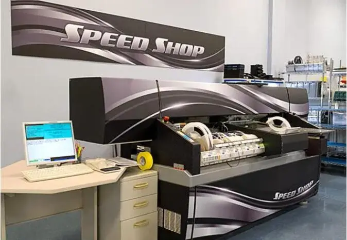
The quality system supports full traceability from panel drawing through first-article inspection and into production. Certifications include ISO 9001:2015, AS9100, JCP, Nadcap accreditation and ITAR registration. IPC-A-610 Class 3 workmanship standards apply to defense and aerospace programs by default.
Pro-Active’s engineering team reviews MLCC placement, fiducial layout, rail dimensions and depanelization method as part of the DFM process before fabrication begins. Programs that enter production with a reviewed panel drawing and documented depanelization method avoid the latent-damage cycle that drives rework and schedule risk.
Frequently Asked Questions
How does panelization affect prototype lead times?
Panelization adds a design step but reduces assembly time per board by allowing multiple units to run through SMT, reflow and inspection in a single pass. For prototype quantities above a modest threshold, or for boards with SMT components near the edge, panelization typically shortens total cycle time compared with building individual boards. Pro-Active’s Speed Shop accommodates panelized prototype builds with short turnaround times, using the same processes as production runs.
Does router depanelization cost more than V-scoring?
Router depanelization often involves more process planning than V-scoring, which can increase per-panel costs depending on design complexity. The relevant comparison is total program cost. Latent solder-joint damage and MLCC cracking from V-score stress can generate rework, field failures and schedule delays that exceed the cost difference between methods. For aerospace, defense and medical programs governed by Class 3 workmanship standards, router depanelization provides the lower-risk choice.
Can Pro-Active Engineering handle onboarding for a new program without disrupting an existing schedule?
Pro-Active’s onboarding process minimizes disruption. New programs typically begin with a pilot build that proves DFM, panelization and process compatibility before volume production transfers. The integrated engineering and manufacturing workflow keeps design reviews, panel drawing approvals and first-article inspections inside one organization, which reduces the coordination overhead that multi-vendor programs carry. Many customers start with a prototype and remain with Pro-Active through the full product lifecycle.
What traceability documentation does Pro-Active provide for regulated programs?
Pro-Active’s quality system produces full traceability documentation linking panel drawing revisions, material certifications, assembly travelers, inspection records and test results. AS9100 and ITAR registration govern documentation practices and access controls. For programs with specific contractual traceability requirements, the engineering team reviews those requirements during onboarding and builds the documentation structure before the first build begins.
Conclusion: Building Reliable Panels from Prototype to Production
Generic panelization introduces mechanical stress that creates latent failures invisible to standard inspection. Routed tabs with rails, generous MLCC keep-outs and controlled router depanelization, documented on every drawing and executed inside an integrated DFM workflow, remove those risks before first-article builds.
Pro-Active Engineering brings ITAR registration, AS9100 certification and a production-process prototype capability together in one US-based facility. Early DFM collaboration on panelization provides a powerful way to reduce program risk on high-reliability builds. Put a production-ready panelization strategy in place from day one.