

Last updated: August 24, 2026
Key Takeaways
- Submitting a complete, rule-compliant data package at the RFQ stage removes CAM holds and revision cycles that compress schedules and raise costs.
- Balanced copper distribution, adequate annular rings, and clearly separated plated and non-plated hole data prevent thermal, registration, and plating defects on prototypes and volume builds.
- Correct solder mask expansion, dam widths, and silkscreen placement protect solderable surfaces and maintain fine-pitch yield from first article through production.
- Complete fiducial, centroid, and revision-consistent documentation supports automated assembly accuracy and traceability under IPC Class 3 and ITAR requirements.
- Pro-Active Engineering runs quick-turn prototypes on the same production processes used for volume builds; submit an RFQ with the completed checklist to accelerate DFM review.
Executive Summary
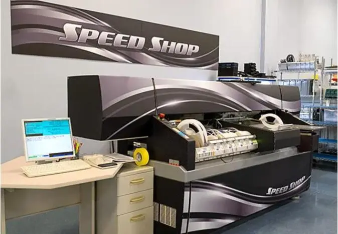
Most DFM failures on quick-turn prototypes trace back to one of eight file-preparation errors. Each error that survives into fabrication adds delay. Errors that survive into volume production add cost and compliance exposure. Pro-Active Engineering operates a dedicated Speed Shop for rapid prototyping alongside full-scale PCB assembly and system integration, creating one partner, one process baseline and one accountable chain of custody from first article to production release.

1. Maintain Balanced Copper Distribution Across All Layers
Balanced copper between layers prevents differential thermal expansion during lamination and reflow. Uncontrolled expansion produces bow and twist that exceeds IPC-6012 flatness requirements. Copper pours, ground planes and fill patterns must be distributed symmetrically about the board mid-plane.
Production-transfer warning: A prototype that passes visual inspection with marginal copper balance may fail automated assembly fixtures at volume. Correcting the stackup after production release forces a full requalification cycle.
2. Ensure Adequate Annular Ring Dimensions Around Every Hole
Annular ring is the copper remaining between a drilled hole edge and the outer boundary of its pad. Standard quick-turn fabricators require a minimum finished annular ring that exceeds the IPC-2221 Class 2 floor. That margin accommodates drill wander and registration tolerances on expedited lines. Class 3 designs for medical and mil/aero applications require larger annular rings on both outer and inner layers to ensure zero breakout under maximum tolerance accumulation.
Because tolerance accumulation varies by fabricator, design teams should apply the annular ring formula and verify the result against the fabricator capability table before submitting files. That check confirms that design margin exceeds the Class 3 floor even under worst-case registration shift.
Production-transfer warning: Marginal annular rings accepted on a prototype run may fall outside tolerance at volume when drill registration shifts across panel positions. Extra margin above the published minimum protects against that risk.
3. Clearly Separate Plated and Non-Plated Hole Requirements
Plated through-holes and non-plated through-holes require different drill sequences and electroplating steps. Mixing PTH and NPTH data in a single Excellon file is a leading cause of electroplating errors during fabrication. Export separate drill files for each type and include a complete tool list with each file.
IPC Class 3 imposes tighter hole-to-hole spacing and hole-to-copper clearance requirements than Class 2. Drill position tolerance is correspondingly tighter. All hole data must reflect the Class 3 intent before release.
Production-transfer warning: A fabricator that infers PTH or NPTH intent from context may plate mounting holes on a prototype. At volume, plated mounting holes can cause grounding faults or mechanical interference with hardware.
4. Apply Appropriate Solder Mask Expansion and Dam Widths
Solder mask expansion in EDA export settings compensates for alignment tolerances during fabrication. Conservative expansion values allow jobs to proceed without CAM intervention. The solder mask dam between adjacent fine-pitch pads is the physical barrier that prevents bridging during reflow. Dam widths that fall below process-stable minimums become a yield risk regardless of paste volume control.
At fine pitch, solder mask strategy must be confirmed with the assembler before finalizing pad definitions. Switching from non-solder-mask-defined to mask-defined pads after layout completion often forces rerouting of the escape pattern.
Production-transfer warning: Inverted solder masks are among the most common causes of CAM holds. Mask polarity should be verified in the Gerber viewer before submission.
5. Position All Silkscreen Elements Away from Solderable Areas
Silkscreen ink deposited over exposed copper pads or within solder mask openings contaminates solderable surfaces and causes unreliable joints. DFM guidelines recommend silkscreen clearance from pads, copper and holes to preserve legibility and prevent ink contamination during fine-pitch prototype builds.
Reference designators and polarity markers must remain legible after assembly. Clipped or overprinted text forces manual inspection at every board and removes the traceability value of the silkscreen layer.
Production-transfer warning: Silkscreen violations that are manually corrected on a prototype run will recur at volume unless the source files are updated. The EDA library must be corrected, not just the output.
6. Include Complete Fiducial and Component Placement Data
Automated pick-and-place equipment requires at least three global fiducials on the board surface to establish coordinate registration. Local fiducials adjacent to fine-pitch components improve placement accuracy on dense assemblies. The centroid or pick-and-place file must include reference designator, X and Y coordinates, rotation angle and side of board for every component.

When fabrication and assembly review occur in parallel, the package should include a current BOM, centroid data and assembly drawings. Fabrication-supporting files and assembly-supporting files must remain clearly separated.
Production-transfer warning: Missing or incorrect centroid data discovered at volume launch delays first-article inspection and can require a full placement program rebuild. Validating the centroid file against the BOM before submission prevents that delay.
7. Submit a Fully Documented, Revision-Consistent Data Package
A complete fabrication package eliminates the back-and-forth that extends quick-turn lead times. IPC-2581 and ODB++ intelligent CAD formats integrate all layer information, netlist topology and component data into a single file that CAM engineers can load directly. Legacy Gerber RS-274X requires layer-by-layer verification. Gerber data has no inherent intelligence, so CAM engineers must manually import files, confirm layer stackup order and reverse-engineer the netlist.
The nine-item file set below removes that guesswork. Each file type supports a specific CAM function, and missing files trigger holds that extend lead time.
- Copper layers (all): Gerber RS-274X or ODB++ format. Top, bottom and all inner layers. Named by layer function.
- Solder mask (top and bottom): Gerber RS-274X or ODB++ format. Mask openings with polarity confirmed. Polarity must be verified in a viewer.
- Silkscreen (top and bottom): Gerber RS-274X or ODB++ format. Reference designators and polarity marks kept clear of solderable areas.
- Board outline: Gerber RS-274X or DXF format. Closed contour with slots and cutouts defined. Missing outlines cause a large share of CAM holds.
- Drill files, plated: Excellon ASCII format. Plated holes with tool list and units. Kept in a separate file from NPTH.
- Drill files, non-plated: Excellon ASCII format. Non-plated holes with tool list and units. Kept in a separate file from PTH.
- Stackup and impedance specification: PDF or fabrication drawing. Layer materials, copper weights, thickness and controlled impedance targets. Missing stackup data forces repeated calculations that extend delivery.
- Fabrication notes: PDF or fabrication drawing. Surface finish, RoHS status, revision and special requirements. All notes must match the rest of the files.
- Release summary or readme: Plain text or PDF. Revision status, approved file list and risk notes. This summary reduces CAM back-and-forth and prevents mismatched revisions.
Production-transfer warning: The fabrication release package must confirm consistency across all files so that layer data, drill files and drawings all reflect the same revision. Mixed-revision packages are a primary cause of production escapes.
8. Verify Every File Against Class 3 and ITAR Traceability Expectations
Complete, revision-consistent documentation forms the base for compliance traceability. Defense, aerospace and medical device programs operate under IPC-A-610 Class 3 workmanship standards. These standards impose tighter inspection criteria than Class 2 on annular rings, drill placement, solder joint geometry and surface finish. IPC Class 3 supports high-reliability products such as medical life-support, military and aerospace applications.
ITAR registration requires that technical data, including Gerber files, fabrication drawings and assembly documentation, be handled under access controls and data-handling procedures that restrict foreign-national access per DDTC requirements. Selecting an ITAR-registered fabricator helps prevent compliance gaps that affect the prototype as a production precursor.
Pro-Active Engineering is ITAR-registered, AS9100 and ISO 9001:2015 certified, JCP certified and Nadcap accredited. The Speed Shop applies those same documented processes, inspection criteria and traceability records to every prototype that volume production uses.
Production-transfer warning: Design teams transitioning from offshore to domestic PCB fabrication must requalify files against the domestic fabricator design rules, material stacks and surface finish capabilities. That step prevents unexpected DFM issues during prototype-to-production handoff. Starting with a domestic, Class 3-capable partner removes that requalification cost.
Download the PDF Checklist
The eight-item checklist above is available as a printable PDF for use during design review and RFQ preparation. Attaching the completed checklist to the data package when submitting files to Pro-Active Engineering accelerates DFM review and reduces first-article cycle time.
Submit an RFQ and include the completed checklist with the package.
Frequently Asked Questions
What constitutes a complete data package for quick-turn fabrication?
A complete quick-turn fabrication package includes Gerber RS-274X or ODB++ files for every copper, solder mask, silkscreen and paste layer. It also includes a board outline file with all slots and cutouts defined. Separate Excellon drill files for plated and non-plated holes with a complete tool list are required. A stackup and impedance specification must cover layer materials, copper weights and board thickness. Fabrication notes must specify surface finish, RoHS status and revision. A release summary should identify the approved file set and flag any special requirements.
When assembly review runs in parallel with fabrication, the package should also include a current BOM, centroid or pick-and-place file and assembly drawings. These assembly files must remain clearly separated from the fabrication-supporting files. Consistent revision labeling across all files is mandatory. Mixed-revision packages are among the most common causes of CAM holds and production escapes.
How do solder mask dam issues affect prototype-to-production transfer?
Solder mask dams are the physical barriers between adjacent fine-pitch pads that prevent solder bridging during reflow. When dam widths fall below process-stable minimums, especially on dense passive clusters, fine-pitch BGAs and compact RF sections, the mask becomes unreliable during exposure and development. That instability leads to bridging defects that may not appear consistently on low-volume prototype runs but emerge as a yield problem at volume.
Because switching from non-solder-mask-defined to mask-defined pads after layout completion typically forces rerouting of the escape pattern, solder mask strategy must be confirmed with the assembler before finalizing pad definitions. Prototype builds that use the same assembly process as volume production surface these issues early, when correction costs remain low. Prototypes built on a different process baseline can hide the problem entirely until production launch.
Can the same design scale to volume without redesign?
A design prepared to production-process standards scales to volume without redesign. Those standards include balanced copper distribution, adequate annular rings, separated PTH and NPTH data, correct solder mask expansion, clean silkscreen placement, complete centroid data and a revision-consistent data package. Redesign risk appears when prototypes run on a simplified or different process baseline than the one used for volume.
Pro-Active Engineering removes that risk by running Speed Shop prototypes on the same SMT and through-hole lines, the same inspection criteria and the same documentation and traceability systems used for full-scale production. What passes first article in the Speed Shop is already qualified for the production floor. Programs in defense, aerospace and medical devices benefit directly from this continuity because requalification cycles under Class 3 and ITAR-controlled conditions are time-consuming and expensive.
The Integrated Onshore Partner for Quick-Turn PCB Fabrication
The eight items in this checklist address the file-preparation errors that cause most CAM holds, prototype-to-production disconnects and compliance gaps on quick-turn PCB programs. Applying them before submission compresses review cycles, protects schedule and ensures that the prototype functions as a true production precursor rather than a one-off build.
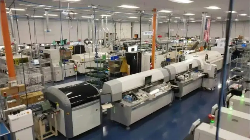
Pro-Active Engineering combines engineering-driven DFM, a dedicated Speed Shop for rapid prototyping and full-scale PCB assembly and system integration under one roof. The company maintains the certifications and process controls described earlier and applies the same processes, inspection standards and traceability records from first prototype through production release. Defense, aerospace and medical device programs gain a single accountable domestic partner that reduces risk across the product lifecycle.
Start a DFM review with Pro-Active Engineering’s engineering team.