
Last updated: August 10, 2026
Key Takeaways for Production-Ready Prototypes
- Closing the design-to-manufacturing gap requires treating every prototype as a production-intent build from the first iteration.
- Embedding DFM checks during schematic and layout prevents costly late-stage redesigns and yield issues.
- Complete fabrication and assembly data packages prevent schedule slips caused by missing or mismatched files.
- Selecting a US partner with integrated design-to-production capability supports compliance, traceability and scalability for regulated industries.
- Pro-Active Engineering delivers this integrated workflow as a single US partner, and teams can start a quick turn PCB design prototyping engagement here.
Audience and Working Definitions
This guide targets lead design engineers, hardware engineers and engineering managers at US defense, aerospace, medical-device and industrial companies. Readers are assumed to have working knowledge of PCB layout and assembly processes.
Key terms used throughout this article are defined below.
- DFM (Design for Manufacturability): Engineering analysis that identifies and resolves manufacturing risk before fabrication begins.
- NPI (New Product Introduction): A structured phase-gate process governing the transition from design to volume production.
- SMT / Through-Hole: Surface mount technology and through-hole technology, the two primary PCB assembly methods.
- BOM (Bill of Materials): A structured list of every component required to build an assembly, including manufacturer part numbers and alternates.
- Gerber / ODB++ / IPC-2581: Standard file formats used to communicate PCB fabrication data to manufacturers.
- Stack-up: The ordered arrangement of copper and dielectric layers in a multilayer PCB.
- FAI (First Article Inspection): A formal verification that the first production-representative unit conforms to design requirements.
- PPAP (Production Part Approval Process): A supplier qualification process confirming production processes can consistently meet requirements.
- IPC Classes: Workmanship and acceptability standards; Class 2 covers general electronics and Class 3 covers high-reliability applications.
- ICT (In-Circuit Test): Automated electrical testing that verifies component placement and solder joint integrity.
- ITAR: International Traffic in Arms Regulations, which govern the export and handling of defense-related technical data and hardware.
- AS9100: The aerospace quality management system standard built on ISO 9001.
- Traceability: The documented chain linking every component lot, process step and inspection record to a finished assembly.
US onshoring trends are accelerating across regulated industries. Unpredictable tariffs, shipping disruptions and geopolitical exposure have made lowest-cost-country models far riskier, while domestic regulatory requirements for ITAR, AS9100 and traceability make US-based manufacturing the required choice for many defense and aerospace programs.
Step 1: Define Functional, Environmental and Compliance Requirements
Every quick turn PCB design prototyping program starts with a clear requirements definition phase. Inputs include functional specifications, environmental operating conditions, target IPC class, applicable certifications and any ITAR or export-control constraints.

Buyers must determine whether the work is ITAR-related, Buy American restricted or contractually domestic before selecting a supplier, because that decision establishes whether a US-only manufacturer is mandatory. For aerospace and defense programs, that determination remains a fixed requirement.
A cross-functional review at this stage, involving design, manufacturing, quality and procurement, establishes the NPI stage-gate baseline. For example, an aerospace program targeting AS9100 compliance defines inspection hold points, traceability requirements and test coverage before layout begins. Resolving these inputs early prevents the most costly disconnects downstream.
Step 2: Apply DFM Checks During Schematic and Layout
DFM analysis delivers the most value while the design remains flexible. DFM review must occur before final design freeze, not after tooling begins.

Structured DFM during layout addresses trade-offs between performance, density, testability and cost. Automated pick-and-place machines require component courtyard clearances that meet IPC-7351 guidelines, and footprints that do not meet those standards cause placement failures that hand-assembly technicians can correct on prototypes but that become systematic defects at volume.
Beyond courtyard clearances, DFM during layout must also address thermal management, panelization and test access. Additional DFM checks during layout include thermal relief on plane-connected pads, panelization planning with fiducial placement, solder mask dam integrity on fine-pitch components and test point accessibility. Common early DFM problems include fine-pitch ICs placed too close together preventing reliable nozzle access and uneven copper distribution causing thermal imbalance and tombstoning.
Pro-Active Engineering integrates DFM into the design phase through its in-house engineering workflow, so manufacturability constraints are resolved before any file is released to fabrication.
Get a quote for DFM-integrated PCB design.
Step 3: Build Complete Fabrication and Assembly Data Packages
Incomplete BOM data, missing reference designators or mismatched Gerber files are among the most common causes of schedule slippage in low-volume US PCB assembly, often adding multiple days before assembly begins. A complete data package removes that delay.

The list below outlines the required files and key DFM considerations for a production-ready quick turn PCB design prototyping submission.
- Fabrication image data (all copper, mask, silk, paste, outline layers): Gerber X2 or ODB++ preferred, RS-274X accepted. All files must belong to the same revision.
- NC Drill files: ASCII Excellon with PTH and NPTH in separate files and a tool list. Board outline dimensions included.
- Stack-up and impedance specification: Fabrication drawing or release note. Missing specs on high-speed designs can extend delivery.
- BOM: Excel (.xlsx) or CSV with MPNs, alternates, DNF flags and MSL ratings. Second sources for every BOM line item require validation.
- Pick-and-place / Centroid file: CSV with reference designator, X/Y, rotation and layer. Rotation angles for polarized components require visual verification against the schematic.
- Assembly drawing: PDF showing component locations, orientations, pin 1 indicators and polarity markers. Both top and bottom views are required.
- Fabrication drawing / release notes: PDF stating board thickness, finish, IPC class, tolerances and special instructions. Without these, manufacturers may price conservatively because of unclear details.
Step 4: Choose a US Partner That Scales From Prototype to Production
Choosing a manufacturing partner that cannot scale creates a critical disconnect: quick-turn prototype shops often lack ISO 9001 or AS9100 systems, while Tier-1 contract manufacturers deprioritize low-to-mid volume runs. A partner that spans both environments prevents that gap.
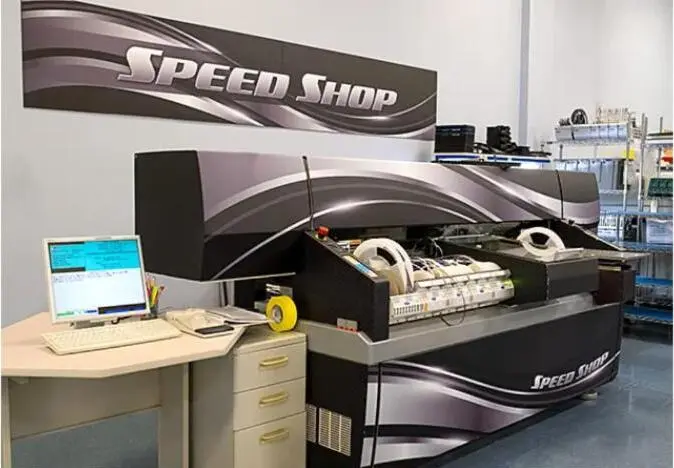
Pro-Active Engineering combines PCB design, rapid prototyping through its dedicated Speed Shop and compliant volume manufacturing under one roof in Sun Prairie, Wisconsin. The company holds ISO 9001:2015, AS9100, ITAR registration, JCP certification and Nadcap accreditation. Its integrated workflow keeps the same engineering team on the design, fabrication, assembly and test, which removes hand-off gaps that cause late-stage redesigns.
For high-reliability sectors like medical devices and aerospace, turnkey assembly with an AS9100-certified and ITAR-registered US manufacturer shifts supply-chain management, ITAR compliance and component traceability to the manufacturer. Pro-Active sources exclusively from authorized distributors and maintains lot-level traceability on every assembly.

Discuss an integrated design-to-production engagement with Pro-Active Engineering.
Step 5: Validate Prototypes With Production-Intent Processes
Prototype validation delivers reliable insight only when the prototype is built using the same processes, materials and equipment as the eventual production run. A working prototype is not the same as a production-ready product; configuration control, phase gates, production-representative builds and pilot runs are required to bridge the gap.
Pro-Active’s Speed Shop builds prototypes using full production SMT and through-hole lines, with AOI and inspection included on every build. Validation steps include FAI to confirm the first production-representative unit conforms to design requirements, ICT to verify component placement and solder joint integrity, and functional test to confirm circuit performance against specification.
For a medical-device program, this validation sequence also incorporates IPC-A-610 Class 3 workmanship inspection, full lot traceability to support FDA documentation requirements and formal test records that travel with the assembly through its lifecycle. X-ray inspection is required for designs using BGAs, LGAs, QFNs with exposed pads or Package-on-Package devices because AOI cannot detect hidden solder joint issues.
Step 6: Plan the Transition to Volume Builds
The transition from prototype to volume production requires formal process planning before the first production order is released. Process FMEA (PFMEA) identifies failure modes in the manufacturing process and assigns controls before they affect yield.
Controlled ramp-up instead of jumping straight to mass production, combined with NPI discipline and validation tracking, prevents late-stage disconnects. Pilot builds at representative volume confirm process capability before full-rate production begins.
Traceability infrastructure must be established at this stage because volume production requires documented proof that every assembly meets specification. That proof depends on four interconnected record types: lot-level component records that link each part to its source, serialized assembly records that track which components went into which unit, test data retention that documents performance verification and engineering change order (ECO) control that maintains configuration integrity across production runs. Pro-Active’s Manex ERP system provides real-time operational analytics and scheduling visibility across the production workflow, supporting the documentation discipline that regulated programs require.
Typical Turnaround by Build Complexity
Turnaround time for quick turn PCB design prototyping varies with board complexity, layer count, assembly type and data package completeness. The list below provides qualitative guidance based on published industry data.
- Simple (low layer count, standard components): Consigned parts. Short timing, often within a few business days when files and parts are ready. Data package completeness drives timing.
- Moderate (mid layer count, mixed SMT and through-hole): Consigned or partial turnkey. Moderate timing, typically several business days on fast-track schedules. Assembly complexity and inspection requirements drive timing.
- High (high layer count, BGAs, controlled impedance, advanced packaging): Turnkey sourcing. Longer timing because component sourcing and specialized processes extend lead time. Component availability and advanced process steps drive timing.
- High-complexity rigid-flex or advanced interconnect: Turnkey with specialized assembly. Extended timing because specialized fabrication and assembly processes require additional time. Fabrication process and validation requirements drive timing.
Pro-Active’s Speed Shop targets prototype delivery in as little as two to five business days for builds where data packages are complete and components are available. Turnaround commitments are confirmed at quoting based on the specific program requirements.
Common Challenges and How Teams Prevent Them
The following challenges appear consistently across quick turn PCB design prototyping programs. Each has identifiable root causes and established mitigations.
Incomplete documentation. Missing CPL files, ambiguous layer naming or mismatched revisions across Gerbers and drill files stall CAM processing before assembly begins. Missing the CPL file or assembly notes is the fastest way to stall an otherwise ready quick-turn PCB prototype build. Prevention: use the essential files checklist in Step 3 and confirm all files share the same revision before submission.
Ambiguous tolerances. Tolerance stack-up causes production assemblies to fail even when individual parts are within spec. Prevention: perform worst-case tolerance analysis on every critical interface before design freeze.
Late design changes. ECOs introduced after prototype validation invalidate prior test data. Any change between the validated prototype configuration and production must be documented and re-validated. Prevention: establish a configuration baseline at DVT and enforce formal change control from that point forward.
Component obsolescence. BOM sourcing failures occur when prototype parts chosen for immediate availability prove to be near end-of-life or single-sourced, resulting in long lead times for volume orders. Prevention: validate second sources for every BOM line item during the prototype phase. Pro-Active uses SiliconExpert for BOM scrubbing and lifecycle risk mitigation.
Underestimated test coverage. Relying on a lead engineer’s bench test does not scale, and a lengthy manual test per unit creates an immediate bottleneck at volume. Prevention: develop parallel test fixture and ICT strategy during the prototype phase, not after production ramp begins.
Unrealistic lead-time assumptions. Turnkey PCB assembly jobs where sourcing harder-to-find components is required take significantly longer than jobs with parts in stock. Prevention: confirm component availability and lead-time alignment with the manufacturer before committing to program schedules.
Measuring Quick Turn Prototyping Success
Objective indicators of a successful quick turn PCB design prototyping workflow include first-pass yield at prototype and pilot stages, solder defect rates tracked by process step, on-time delivery against committed dates, ECO frequency after design freeze, cost variance against program budget and field-return trends over the product lifecycle.
Early NPI metrics focus on yield stability and process repeatability across pilot builds. Longer-term reliability measures shift to field-return rates and mean time between failures. Both sets of metrics should be tracked separately and reviewed at each NPI stage-gate. Pro-Active’s integrated workflow supports this tracking through its Manex ERP system and documented quality management processes.
Advanced Workflow Enhancements for Mature Programs
Programs with mature NPI processes can pursue additional workflow enhancements. Digital-thread data continuity, which maintains a single, revision-controlled data set from schematic through production, eliminates the version mismatches that cause CAM holds and assembly errors. Model-based definition (MBD) replaces 2D drawing packages with annotated 3D models, reducing interpretation errors during manufacturing transfer.
Advanced test strategies such as boundary-scan, flying probe and automated functional test systems extend coverage beyond ICT and reduce reliance on manual inspection. Tighter supplier integration through shared ERP visibility and consigned inventory programs shortens material kitting cycles for repeat production orders.
These capabilities require established process baselines and should be introduced through controlled pilots rather than applied to first-article programs. Pro-Active’s engineering team can assess readiness and sequence these enhancements within an existing program structure.
Frequently Asked Questions
What factors most affect turnaround time for quick turn PCB design prototyping?
Data package completeness represents the single largest variable. Programs with complete Gerber or ODB++ files, a fully populated BOM with manufacturer part numbers and alternates, a correct pick-and-place file and clear assembly drawings move directly into production. Programs with missing or mismatched files enter a review cycle that adds time before assembly begins. Board complexity, layer count, component availability and required inspection steps also affect turnaround. Pro-Active’s Speed Shop is structured to minimize internal processing time when the data package is complete.
How does ITAR registration affect the choice of PCB manufacturer for defense and aerospace programs?
ITAR registration is a legal requirement for manufacturers handling defense-related technical data and hardware. US export-control rules treat design and manufacturing information for defense articles as controlled technical data. An ITAR-registered manufacturer maintains documented access controls, data-handling procedures and personnel training records to protect that data. Programs subject to ITAR, DFARS or covered defense information requirements must use a US-based, ITAR-registered manufacturer. Pro-Active Engineering is ITAR-registered and maintains the documentation and process controls required for regulated defense and aerospace programs.
What is the difference between a prototype built for proof-of-concept and a production-ready PCB prototype?
A proof-of-concept prototype validates circuit function, typically using hand-assembled or bench-built methods. A production-ready PCB prototype is built using the same automated assembly processes, materials and inspection methods as the eventual production run. The distinction matters because assembly defects, thermal issues and tolerance failures that are masked by hand assembly become systematic yield problems at volume. Pro-Active builds prototypes through the same production processes described in Step 5, so validation data from the prototype directly predicts production performance.
When should a program consider switching suppliers or initiating a redesign?
A supplier change is warranted when the current partner cannot demonstrate the certifications, process controls or scaling capability required for the next program phase, such as when a prototype shop lacks AS9100 or ICT capability needed for production. A redesign is warranted when first-pass yield data, DFM analysis or field-return trends indicate that the current design cannot meet reliability or cost targets through process improvement alone. Both decisions should be driven by objective metrics from the NPI stage-gate review rather than schedule pressure alone.
How does Pro-Active Engineering support programs that start with prototypes and scale to volume production?
Pro-Active manages the full product lifecycle under one roof. Programs begin with PCB design and DFM integration, move into rapid prototyping through the Speed Shop and transition to low-to-high volume assembly using the same engineering team, quality system and traceability infrastructure. This continuity removes the hand-off gaps that cause redesigns and compliance exposure when programs transfer between separate design and manufacturing vendors. Customers retain full oversight through regular design reviews, real-time scheduling visibility via Manex ERP and transparent documentation throughout the program.
Conclusion and Next Step
The prototype-to-production gap closes through a structured workflow that embeds DFM from the first layout, prepares complete fabrication and assembly data packages, validates prototypes with production-intent processes and plans the volume transition through PFMEA and traceability infrastructure.
Pro-Active Engineering provides that workflow as a single US partner, integrating design, rapid PCB prototyping via its Speed Shop and the certified manufacturing infrastructure described in Step 4. Defense, aerospace, medical-device and industrial programs benefit from the same engineering team, quality system and traceability infrastructure from first prototype through volume production.
Start an integrated quick turn PCB design prototyping workflow with Pro-Active Engineering.