
Last updated: August 6, 2026
Key Takeaways for Quick-Turn PCB Prototyping
-
Quick-turn PCB prototyping compresses lead times by prioritizing builds on dedicated lines and removing offshore shipping delays.
-
Complete documentation and early DFM reviews prevent the most common production holds and schedule slips.
-
Domestic partners with integrated engineering and production close handoff gaps, reduce total cost of ownership and use production-grade processes.
-
Comprehensive test coverage and traceability records created during prototyping carry forward to volume manufacturing without requalification.
-
Start a project discussion with Pro-Active Engineering’s integrated design-to-production team.
Step 1: Lock Functional, Environmental and Compliance Requirements
Fast, production-ready prototyping starts with a complete requirements baseline before layout work begins. Inputs include operating environment, power and signal integrity targets, mechanical constraints and the regulatory framework for the end product.
Compliance requirements for defense, aerospace or medical programs shape every downstream decision. AS9100D builds on ISO 9001 and adds requirements for risk management, product safety, traceability and counterfeit prevention for aerospace and defense suppliers. ITAR regulations require that defense-related technical data remain within a registered domestic supply chain, and transmitting design files to a nonregistered foreign facility constitutes a federal violation. Early identification of these requirements determines which partners, materials and processes qualify from day one.
The output of this step is a written requirements document that cross-functional stakeholders in design, procurement and program management have reviewed and approved. This document must resolve key decision points before layout begins, including IPC workmanship class, surface finish and whether the program requires certifications such as AS9100, Nadcap or JCP. Freezing these decisions early prevents midcycle changes that restart the prototyping timeline.
Step 2: Build a Complete, Error-Checked Design Package
Complete, accurate documentation keeps quick-turn prototyping on schedule. Incomplete documentation is the most common cause of production holds, and many prototype assembly issues trace back to incorrect BOM entries.

A complete fabrication and assembly package includes the following elements:
-
RS-274X Gerber files for all copper, solder mask, silkscreen and board outline layers
-
Excellon NC drill files with plated and nonplated holes clearly separated
-
Fabrication notes specifying material, thickness, copper weight, surface finish, impedance requirements and stackup
-
A BOM in Excel or CSV format listing manufacturer part numbers, reference designators, quantities, package types and approved alternates
-
A pick-and-place (centroid) file with X/Y coordinates, rotation angle and board side for every SMD component
-
Assembly drawings in PDF showing component orientation, polarity markers and both board sides
-
A readme or manufacturing notes file communicating special instructions, revision notes and panelization preferences
Beyond submitting individual files, intelligent formats such as ODB++ or IPC-2581 can consolidate layer images, netlist data, drill information, stackup attributes and component details into a single file, which reduces CAM interpretation errors. Confirm format acceptance with the manufacturing partner before submitting either format as the sole deliverable. Running a DRC check before export and previewing Gerber files with a viewer catches common errors such as missing layers or mixed unit systems before they reach the factory floor.
Step 3: Run DFM and DFT Reviews Before RFQs
Early integration of DFM in PCB prototyping catches manufacturability issues before fabrication or assembly begins and prevents prototype lead times from stretching from days into weeks. A DFM review examines component footprint accuracy, pad geometry, clearances, via placement, solder mask openings, polarity markings and panelization against the production equipment’s actual process parameters.
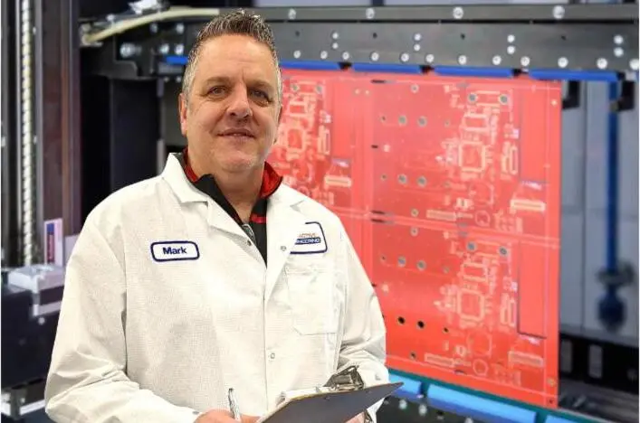
Each engineering query generated after submission typically adds days of communication and waiting time, so early review becomes a direct lever on the schedule. Early-stage DFM analysis before sending RFQs eliminates back-and-forth emails and RFQ revisions and cuts lead time lost to communication.
A strong Design for Test implementation during the PCB layout phase can increase in-circuit test coverage significantly by ensuring adequate test point accessibility. DFM and DFT reviews work best when conducted against the same equipment and process parameters used in production runs. Findings then transfer directly to volume manufacturing without a second review cycle.
Start a DFM review with Pro-Active Engineering’s integrated design and manufacturing team.
Step 4: Choose a Domestic, Integrated Engineering and Production Partner
Partner selection has the greatest impact on quick-turn prototyping performance. Offshore PCB assembly introduces hidden total cost of ownership expenses, including international freight, customs duties, tariffs, inventory holding costs and full costs of rework or scrap when defects surface at distant facilities. Transferring design files to offshore facilities also carries documented risks of unauthorized reverse engineering and unenforceable foreign NDAs.

A domestic partner with integrated engineering and production closes the communication gaps that fragmented vendor chains create. Evaluation criteria for a quick-turn PCB partner include:
-
ITAR registration and documented data-handling controls for defense and aerospace programs
-
Certifications covering quality management, workmanship and traceability, including ISO 9001:2015, AS9100, IPC-A-610 Class 2/3 and J-STD-001
-
A dedicated rapid prototyping line that uses full production processes, not simplified substitutes
-
In-house DFM capability integrated into the design phase, not added at submission
-
Advanced interconnect and thermal management capabilities for high-density or high-power designs
-
Scalable capacity from single-unit prototypes through low-to-mid volume production under one roof
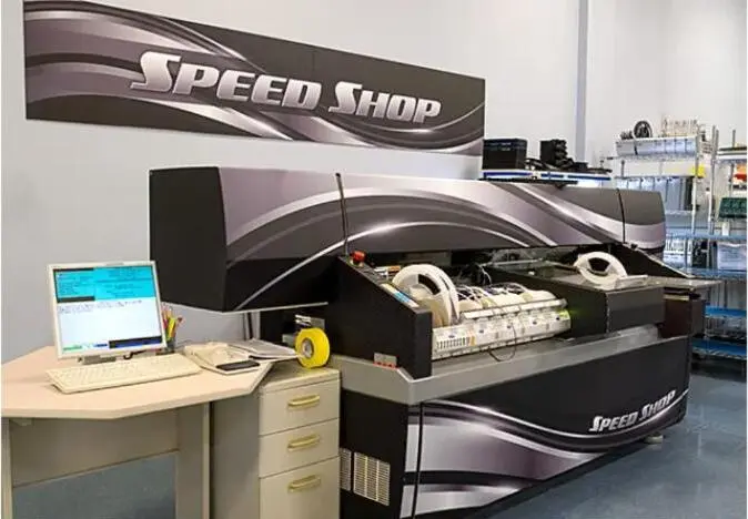
Pro-Active Engineering consolidates PCB design and engineering, rapid prototyping through its dedicated Speed Shop, SMT and through-hole assembly, conformal coating, functional testing and box build into a single workflow at its Sun Prairie, Wisconsin, facility. The company holds ISO 9001:2015, AS9100, ITAR, JCP and Nadcap certifications and maintains IPC-A-610 Class 2 and Class 3 workmanship standards. Prototypes run on the same processes and equipment as production, so validated designs transfer to volume manufacturing without process-change risk.
Step 5: Validate Prototypes with Structured Test and Traceability
Every aerospace and defense PCB assembly must maintain a production record tied to the board serial number that includes component lot numbers, paste print measurements, reflow profile traces, AOI and X-ray results and electrical test data to support root-cause analysis of any field failure. Applying the same discipline to prototypes produces traceability records that carry forward into production.

Test coverage for quick-turn prototypes should include:
-
Automated optical inspection after assembly to catch placement and solder defects
-
Flying probe or in-circuit testing for net-level electrical verification
-
Functional testing against defined pass-fail criteria from the requirements document
-
X-ray inspection for BGA joints and hidden solder connections where applicable
Using the same materials for prototypes as for production ensures that electrical, thermal and mechanical performance during prototyping matches production results and avoids unexpected behavior from material substitution. Test specifications, including pass-fail criteria for each test method, should appear in the manufacturing release package before prototype fabrication begins.
Step 6: Capture Prototype Lessons and Plan for Scale
Prototype activity generates data that reduces production risk when captured and applied. Engineering change orders, DFM findings, test failures and component substitutions should be documented, reviewed and incorporated into the production release package before volume manufacturing begins.
Key outputs from this step include an updated BOM with confirmed manufacturer part numbers and approved alternates, revised Gerber files reflecting any engineering changes, documented test coverage results and a lessons-learned record that the manufacturing partner can reference during production planning. DFM findings documented and tracked through prototype and pilot stages transfer lessons to volume manufacturing, which reduces first-article failures and shortens the NPI timeline.
When the prototype and production partner share the same facility, process parameters and quality system, this transition becomes a documentation exercise rather than a supplier qualification event. Vendor fragmentation forces requalification at each handoff and adds schedule risk and cost that an integrated partner removes.
Discuss your prototype-to-production transition with Pro-Active Engineering’s integrated workflow team.
Common Quick-Turn Challenges and How Teams Address Them
Several recurring issues extend quick-turn timelines or compromise prototype quality. Early recognition allows program teams to act before these issues affect the schedule.
Incomplete design files. Incomplete Gerber files and BOM mismatches at submission create manufacturing holds per round trip and extend lead times in rapid PCB prototyping. As noted in Step 2, a complete, verified package at the outset prevents this category of delay.
Late engineering change orders. ECOs issued after fabrication begins require scrapping in-process boards and restarting the cycle. Freezing the design before submission and routing any changes through a formal review process limits late ECO exposure.
Component availability gaps. Using obsolete or hard-to-source components introduces risk of delays or redesigns when moving from prototyping to production. BOM scrubbing against live distributor inventory and lifecycle data during the DFM phase identifies substitution risks before they become schedule problems.
Insufficient test coverage. Prototypes that pass bench testing but lack structured functional test coverage can mask reliability issues that appear at volume. Defining test specifications in the requirements document and building test fixtures in parallel with prototype fabrication closes this gap.
Practical Frameworks and Tools for Faster Prototyping
Several established frameworks support a disciplined quick-turn prototyping workflow and reduce schedule risk.
DFM checklists. A DFM checklist aligned to the manufacturing partner’s process capabilities covers conductor routing, layer stackup symmetry, hole aspect ratios, solder mask geometries, copper clearances, fiducial placement and panelization. Early application of DFM rules generates fabrication data packages within the selected factory’s process limits and minimizes financial losses from design changes, material waste and production downtime.
NPI stage-gate models. A new product introduction stage-gate model assigns defined inputs, outputs and approval criteria to each phase: requirements, design, DFM review, prototype build, validation and production release. Gate reviews prevent advancement until each phase is complete and reduce the risk of late-stage surprises.
IPC workmanship standards. IPC-A-610 Class 3 requires no acceptable defects and continuous operation for aerospace and defense assemblies. J-STD-001 governs soldering requirements, and IPC-7711/7722 covers rework and repair. Specifying the applicable IPC class in the requirements document ensures that the manufacturing partner applies the correct acceptance criteria from the first prototype build.
Frequently Asked Questions
What factors most affect quick-turn PCB prototype lead times?
Layer count, board type, surface finish selection, via structures and documentation completeness drive most lead times. Boards with more layers or multiple lamination cycles require additional processing steps that extend the schedule. Surface finishes with longer plating cycles add time compared with simpler options. Blind and buried vias require sequential lamination and add meaningful time per additional cycle. A complete, verified documentation package at order placement removes the engineering query cycles that cause the most preventable delays in rapid PCB prototyping.
What compliance certifications should a domestic quick-turn PCB partner hold for defense and aerospace programs?
Defense and aerospace programs typically require a partner holding AS9100D for quality management, ITAR registration for controlled technical data, IPC-A-610 Class 3 workmanship certification and J-STD-001 for soldering. JCP certification, documented on DD Form 2345, is required for certain military programs. Nadcap accreditation covers specific special processes. First article inspection per AS9102B validates that manufacturing processes can consistently produce boards to specification before production begins. Confirming that a partner holds all applicable certifications before program start avoids disqualification later in the program lifecycle.
How does an integrated design-to-production partner reduce total cost of ownership compared with a fragmented vendor chain?
Fragmented vendor chains introduce communication gaps at every handoff between design and fabrication, fabrication and assembly and assembly and test. Each gap creates a potential source of misinterpretation, rework and schedule delay. An integrated partner applies DFM during the design phase, builds prototypes on production equipment and carries traceability records forward into volume manufacturing without requalification. This approach reduces respins, lowers rework costs, shortens NPI timelines and provides a single point of accountability for program performance. Offshore options may offer lower unit prices, but tariffs, freight, customs delays and quality-related rework costs narrow or remove that advantage for regulated, low-to-mid volume programs.
How does a quick-turn prototype built on production processes differ from a simplified prototype build?
A prototype built on production processes uses the same materials, equipment, solder chemistry, inspection methods and quality documentation as the production run. Electrical, thermal and mechanical performance validated during prototyping then reflects actual production behavior. Simplified prototype builds that use substitute materials, manual assembly or relaxed inspection can pass bench testing while masking reliability issues that appear when production-grade processes apply. Building prototypes on production processes removes this gap and allows validated designs to transfer to volume manufacturing without process-change risk.
What should engineering teams look for when evaluating a quick-turn PCB partner’s scalability?
Scalability evaluation should confirm that the partner operates dedicated rapid prototyping capacity separate from production lines, supports a minimum order quantity of one unit for R&D builds and can transition the same design to low-to-mid volume production without changing the manufacturing process or quality system. Partners with advanced interconnect capabilities such as wire bonding, flip chip assembly and high-density hybrid assemblies, along with thermal management solutions, support programs that grow in complexity as they scale. A single facility housing design, prototyping, assembly, testing and system integration under one quality management system provides a predictable scalability path for regulated programs.
Conclusion
Quick-turn PCB prototyping delivers value when the prototype accurately predicts production behavior. That outcome depends on clear requirements, complete documentation, early DFM integration, disciplined test coverage and a manufacturing partner whose prototype processes match production. Vendor fragmentation undermines these conditions by introducing handoff gaps, communication delays and inconsistent process parameters at every transition.
Pro-Active Engineering applies this integrated approach at its ITAR-registered, AS9100-certified Sun Prairie facility and removes the vendor fragmentation that introduces risk at every handoff. Defense, aerospace, medical and industrial programs gain a single accountable partner with the certifications, advanced capabilities and production-grade processes needed to move from validated prototype to scalable production without surprises.
Start a project discussion with Pro-Active Engineering’s team.