
Last updated: August 16, 2026
Key Takeaways for Aerospace ICT Selection
- Aerospace ICT systems must provide documented fault coverage, AS9100 traceability and calibration records that remain retrievable for the required retention period.
- Five evaluation criteria, including fault coverage depth and traceability architecture, should guide platform selection instead of brand preference.
- High-density boards require DFT review plus techniques such as vectorless testing and boundary scan when physical probe access is limited.
- Low-volume, high-mix aerospace builds benefit from flying probe systems that remove fixture costs and support rapid engineering changes without requalification.
- Pro-Active Engineering integrates ICT, flying probe, boundary scan and full AS9100 documentation in a single ITAR-registered facility; align test strategy with audit-ready traceability from day one.
Five Evaluation Criteria for High-Reliability Aerospace PCBAs
Selecting ICT equipment for aerospace programs works best when teams evaluate five criteria in sequence instead of defaulting to a single platform specification.
- Fault coverage depth. Industry studies show ICT effectiveness varies across manufacturing sites, depending on the defect set. Coverage percentages measure how many known defect types a test catches within a specific dataset, not how many nets are physically probed. A coverage report must separately list directly probed nodes, component measurements, vectorless pins, scan-supported networks and board-revision exclusions.
- Boundary-scan integration. Boundary scan complements ICT by expanding coverage on dense digital nets where physical probe access is limited. It enables interconnect tests, bus-wire tests and silicon nails without added fixture complexity. It does not replace ICT and cannot test analog circuits.
- AS9100 traceability architecture. Test systems that store only local files with no unique linkage to serial or lot create a common traceability failure mode because auditors cannot reconstruct the as-built history for a specific unit during field failures. To prevent this gap, the platform must link board serial or lot identifier, fixture and program revision levels, measured values versus programmed limits, diagnostic output and retest results to a single retrievable record.
- Fixture economics. Dedicated bed-of-nails fixtures carry upfront tooling cost and require requalification when board revisions move probe targets. A PCB revision directly affects the probe map, fixture plate, fixture support, wiring, component models and programmed limits. Programs with frequent engineering changes must include requalification cost in fixture economics.
- Volume fit. For aerospace and medical device projects with low production volumes, flying probe testing delivers equivalent coverage to fixture-based ICT for shorts, opens, component values and polarity while requiring no fixture investment. High-volume programs with stable revisions recover fixture cost through throughput gains.
High Pin-Count Boards: Managing Coverage and Mechanical Strain
The fault coverage criterion becomes especially challenging on high-density assemblies. Conventional 100 percent test access is often no longer achievable on modern, densely populated boards, so Design for Testability review must occur before PCB layout finalization. When probe access is limited by high component density, missing test points or BGA components without vias, ICT coverage decreases.
For inaccessible circuitry, complementary techniques such as vectorless opens (VTEP), boundary scan or JTAG and IEEE 1149.6 for AC-coupled or differential networks can raise effective fault coverage. These methods depend on supported devices, accessible JTAG interfaces and valid BSDL data.
Fixture-induced board strain creates a separate risk on high-density assemblies. Strain gauge testing during fixture development is recommended for boards with large BGAs or small passive components. Measured strain above accepted thresholds indicates risk of cracked capacitors or BGA pad cratering that can produce latent field failures after passing ICT.
Low-Volume, High-Mix Builds: Applying Flying Probe and Flexible ICT
Low-volume, high-complexity assemblies often remain on flying probe until revision stability supports a fixed fixture. Flying probe systems remove fixture tooling cost and accommodate frequent engineering changes without requalification. Flying probe ICT systems can extend to boundary scan testing, on-board memory programming, AOI and functional tests, so multiple test solutions run from a single platform.
The transition from flying probe to a dedicated fixture functions as a program-level decision driven by revision stability, unit volume and throughput requirements. Programs that move from prototype to production without a defined transition plan risk carrying flying-probe cycle times into volume builds, which increases test cost per unit. Pro-Active Engineering supports that transition by integrating DFM review, DFT planning and fixture development within a single workflow so the test strategy scales with the program.
AS9100 Audit Trails: Documentation and Configuration Control
The execution layer creates and links most AS9100 traceability evidence by capturing as-built history for each part or assembly at the time work occurs. It enforces routing sequences and links part numbers, serial numbers, work orders, nonconformances, tools and gages into coherent genealogy.
AS9100 Rev D Section 7.1.5 requires that monitoring and measuring resources be calibrated at specified intervals against measurement standards traceable to international or national standards, with records including measurement uncertainty values retained. Every instrument in a compliant test system must maintain a calibration record traceable to national standards. The test executive checks calibration due dates at startup and blocks test execution if any instrument is out of calibration.
Revision control holds equal importance. For long-life aerospace programs, PCB revisions, component substitutions under obsolescence waivers, fixture condition and program revisions must remain aligned so that replacing an obsolete part does not introduce an incorrect component model, limit or probe map. Each substitute part requires its own verified model and limit set.
Comparing Teradyne, Keysight, Seica and SPEA for Aerospace ICT
Teradyne TestStation and ICT platforms appear widely in high-volume aerospace and defense production environments. Their strength lies in throughput and a mature ecosystem of fixture tooling and test libraries. The trade-off involves fixture investment and the engineering overhead required to maintain program files across board revisions.
Keysight i3070 systems provide a fixture-based ICT platform with strong analog measurement capability and established boundary-scan integration. Keysight guidance acknowledges the test access challenges described earlier, and the platform supports vectorless and JTAG extensions to address coverage gaps on complex assemblies.
Seica Pilot flying probe systems suit low-volume, high-mix aerospace builds where fixture economics are unfavorable. Seica platforms apply the fixtureless approach described earlier to these programs and support boundary scan, in-system programming and functional test extensions from a single system, which reduces the number of separate test stations required for prototype and early-production builds.
SPEA flying probe and combined systems offer high-speed multi-probe architectures that reduce cycle time on complex boards without requiring dedicated fixtures. SPEA platforms support aerospace and defense programs where board complexity and access constraints make fixture-based ICT impractical at low volumes.
Platform selection should follow the five-criteria evaluation framework rather than brand preference. The platform that delivers the highest traceable fault coverage for a specific board design, production volume and revision cadence becomes the correct choice for that program.
Pro-Active Engineering: Integrated ICT and Traceable Test Workflow
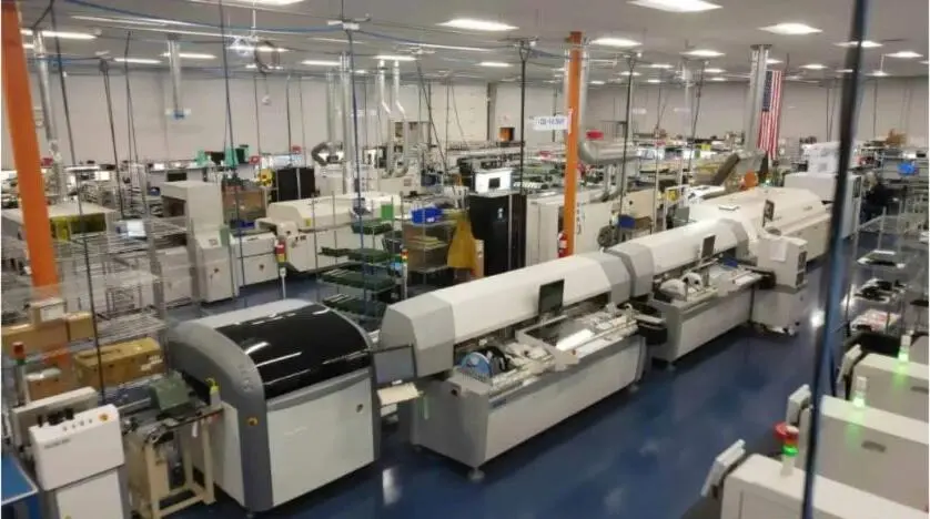
Pro-Active Engineering operates in-house flying probe, ICT and functional test capabilities alongside boundary-scan integration and AOI within a single AS9100-certified facility in Sun Prairie, Wisconsin. DFM and DFT review begin at the design phase so test point placement, JTAG chain design and probe access are resolved before layout freeze instead of after first article.
Traceability runs from incoming material lot through assembly, test, inspection, rework and shipment within a single documentation system. Test records capture board serial or lot identifier, fixture and program revision levels, measured values versus programmed limits, diagnostic output, confirmed cause, repair action and retest result, which matches production ICT traceability standards.
As an ITAR-registered domestic manufacturer, Pro-Active Engineering maintains access controls, data-handling procedures and personnel training records consistent with DDTC requirements. Customers on sensitive aerospace and defense programs gain a single accountable partner without the IP exposure and audit complexity that accompany offshore or multi-vendor supply chains.
Pro-Active Engineering also integrates SAE AS5553B counterfeit avoidance methodology and uses SiliconExpert for BOM scrubbing and component lifecycle risk management. This approach reduces the probability that an obsolescence substitution introduces an unverified component into a traceable aerospace build.
Connect with Pro-Active Engineering’s test engineering team to map ICT, flying probe, functional test and boundary-scan requirements to an integrated documentation system.
RFQ Checklist for Aerospace ICT Programs
This checklist supports RFQ preparation for aerospace PCBA ICT services. Each item maps directly to AS9100 audit and documentation requirements.
- Board serial or lot identification scheme and required traceability depth (lot-level vs. unit-level)
- Customer-specified record retention period under AS9100 clause 7.5.3
- ICT coverage report format: method set, numerator, denominator and board revision stated separately
- Boundary-scan requirements: JTAG chain diagram, device list, BSDL file versions and accessible TAP interfaces
- Fixture strategy: bed-of-nails, flying probe or hybrid, with strain management plan for high-density assemblies
- Calibration traceability requirements: instrument calibration certificates with measurement uncertainty traceable to NIST or equivalent
- Revision control plan: process for updating probe maps, component models and programmed limits when board revisions or obsolescence substitutions occur
- Functional test requirements: powered test scope, interface conditions and firmware revision linkage
- Applicable acceptance standards: IPC-9252, IPC-A-610 Class 3, RTCA DO-160 environmental screening or MIL-STD-202 as applicable
- Nonconformance workflow: NCR linkage to serial number, disposition record and retest evidence
- ITAR and data-handling requirements: domestic manufacturing, access controls and documentation practices
- First Article Inspection scope and AS9102 measurement equipment calibration requirements
Next Steps: Reducing Risk with One ICT Partner
Vendor fragmentation, incomplete traceability and late-stage manufacturability issues create primary sources of program risk in aerospace PCBA production. Pro-Active Engineering reduces those risks by consolidating ICT, flying probe, functional test, boundary scan, DFM and AS9100 documentation into a single domestic workflow.

Programs that engage Pro-Active Engineering at the design phase gain DFT planning, test point placement and coverage analysis before layout freeze, the point where changes cost less and deliver stronger impact.
Begin the conversation with Pro-Active Engineering’s aerospace test engineering team to discuss specific ICT requirements.
Frequently Asked Questions
What is the difference between ICT fault coverage and test access coverage for aerospace PCBAs?
Fault coverage measures how many known defect types a test program can detect within a defined defect set for a specific board design. Test access coverage measures how many physical nodes or nets on the board probes can reach. The two numbers relate but do not match directly. A board with 80 percent physical probe access may achieve lower fault coverage if the inaccessible 20 percent includes critical digital interconnects.
For aerospace programs, the coverage report must state the method set used, such as direct probe, vectorless, boundary scan or a combination, along with the numerator, denominator and board revision. Combining all methods into a single undefined percentage does not satisfy AS9100 audit requirements and hides the actual risk profile of the test strategy.
When should an aerospace program use flying probe instead of a dedicated ICT fixture?
Flying probe suits cases where production volumes are low, board revisions occur frequently or fixture tooling cost cannot be justified against the planned unit count. Flying probe systems require no fixture investment, accommodate engineering changes without requalification and support full traceability for shorts, opens, component values and polarity. The trade-off involves longer cycle time per board compared with a bed-of-nails fixture.
Programs that reach revision stability and sufficient volume can transition to a dedicated fixture to recover throughput. Pro-Active Engineering supports that transition within a single workflow so the test strategy scales with the program without a supplier change or documentation restart.
How does boundary scan integrate with ICT for high-density aerospace assemblies?
Boundary scan, based on the IEEE 1149.1 standard, tests interconnections between ICs without physical probes by shifting test vectors through a scan chain built into each compliant device. It works best on dense digital nets such as BGAs, FPGAs, DDR memory and fine-pitch processors where physical probe access is limited or absent. When combined with ICT, boundary scan enables interconnect tests, bus-wire tests and silicon nails without added fixture complexity.
Boundary scan does not replace ICT for analog circuits, RF paths or non-JTAG passives. A complete test strategy for a high-density aerospace assembly typically combines ICT for passive and analog nodes, boundary scan for digital interconnects, vectorless techniques for inaccessible nets and functional test for powered behavior. Boundary scan coverage depends on proper JTAG chain design, accessible TAP interfaces and valid BSDL files for each device in the chain, so DFT planning must begin at the schematic stage.
What AS9100 documentation does Pro-Active Engineering produce for ICT test records?
Pro-Active Engineering produces ICT test records that capture board serial or lot identifier, fixture and program revision levels, individual measurement results with measured values and programmed limits, diagnostic output, confirmed fault cause, repair action and retest result. Calibration traceability for all test instruments is maintained with records traceable to national standards.
Records link to the assembly’s material lot, production history, inspection results and shipment records within a single documentation system. Nonconformances link to specific serial numbers with disposition records and retest evidence. This record structure supports AS9100 clause 7.5.3 retention requirements and provides the retrievable genealogy that auditors and customers require for source inspection, field investigation and configuration history reconstruction.
How does Pro-Active Engineering handle component obsolescence in long-life aerospace ICT programs?
Component obsolescence creates persistent risk in long-life aerospace programs because a substitute part affects the ICT fixture probe map, component model, programmed limits and verification work. Pro-Active Engineering uses SiliconExpert for BOM scrubbing and component lifecycle risk management to identify obsolescence risk before it reaches production.
When a substitution is required, the replacement component receives its own verified model and limit set before the updated program releases to production. Revision control links the updated program revision to the board revision and the specific substitution event so the traceability record reflects the actual component installed at each serial number. This process satisfies AS9100 configuration management requirements and prevents the introduction of unverified component models into a traceable aerospace build.