
Key Takeaways for Wire Bond Validation
- Wire bonding process validation qualifies mechanical, electrical and environmental reliability so production bonds stay repeatable, traceable and standards compliant.
- Process-window characterization and DOE planning map bonding force, ultrasonic energy and material properties into a statistically defensible production window.
- MIL-STD-883 pull and shear testing, combined with reliability sequences including BAMFIT, confirm bond integrity under harsh aerospace, defense and medical conditions.
- Visual, automated and AI-driven inspection plus statistical capability reporting provide documented evidence for Nadcap, ITAR, AS9100 and ISO 13485 compliance.
- Pro-Active Engineering integrates the full validation workflow under one accredited roof; request a quote to begin mapping wire bonding validation requirements.
Characterizing the Wire Bond Process Window
Process-window characterization defines the parameter range where a wire bonding process produces conforming bonds consistently. This work depends on several linked variables. Wire material and diameter set the mechanical behavior of the wire and bond. Bonding force and ultrasonic energy control weld formation at the interface. Temperature, loop geometry and substrate surface condition further shape bond quality and must be evaluated together.
Material selection drives much of this effort. Electrolytic wire bondable gold supports wire bonding in military and defense PCB manufacturing. Aluminum wedge bonding serves power electronics and high-current assemblies because it matches aluminum bond pads and supports higher current density. Each material family receives its own characterized window.
Acceptance criteria established during characterization define the production-ready window. These criteria cover minimum bond pull strength, ball shear strength, visual loop profile and placement accuracy. Any parameter combination that produces bonds outside those criteria is removed from the validated window before qualification testing begins. Once the initial parameter space is understood, the program can move into structured DOE planning.
DOE Planning for Wire Bond Qualification
A structured Design of Experiments reduces the number of builds needed while still generating statistically defensible data. This sequence fits high-reliability wire bond qualification programs.
- Define the response variables: pull force, shear force, failure mode distribution and loop geometry measurements.
- Identify control factors and their ranges: bonding force, ultrasonic power, time, temperature and wire feed parameters.
- Select a fractional factorial or full factorial design based on factor count and available sample budget.
- Determine sample size that delivers adequate statistical power at the required confidence level.
- Run the DOE on production-representative substrates using production equipment and operators.
- Analyze main effects and interactions, then identify the center point of the robust process window.
- Confirm the selected settings with a verification run before formal qualification testing.
Statistical power requirements for aerospace and defense programs exceed typical commercial baselines. Sample plans account for lot-to-lot material variation and equipment drift across the qualification period.
Start a DOE planning review with Pro-Active Engineering’s validation team.
MIL-STD-883 Pull and Shear Test Protocols
MIL-STD-883 Method 2011 defines the wire bond pull test and Method 2023 defines the ball shear test for military, space and high-reliability commercial electronics.
In the Method 2011 pull test, a calibrated hook sits under the wire bond loop and pulls upward with increasing force until the bond breaks. The test records pull force and failure mode. A wire break in mid span or at the neck shows that welds exceeded the strength of the wire. A clean bond lift from the pad shows that the weld formed the weak point.
Failure mode classification carries equal weight with force values. The location of failure reveals process behavior that raw force numbers can hide.
In the Method 2023 ball shear test, a flat tool pushes laterally against the ball bond at the die pad level. The test records the shear force at failure. Ball bond shear testing detects intermetallic-layer problems and poor bonding conditions more sensitively than pull testing.
Minimum force values follow wire diameter and ball size per the standard. MIL-STD-883 acceptance requires both minimum force values and acceptable failure modes. Ball bond lift, wedge bond lift or pad lift remain unacceptable regardless of recorded force.
Sampling plans under MIL-STD-883 require destructive bond pull testing on twenty-two bonds from a minimum of four units per production lot. Statistical process control monitoring applies at the start and completion of each assembly lot and at defined intervals. Results appear in a formal report with examination findings, measurements, photographs and pass or fail determinations tied to MIL-STD-883 requirements to support lot acceptance.
Reliability Testing and BAMFIT Sequences
Reliability testing exposes validated bonds to environmental stresses expected in service. For new wire bond processes or materials, qualification per MIL-STD-883 or JEDEC includes temperature cycling, high-temperature storage, humidity exposure for nonhermetic packages and mechanical shock. Pull and shear strengths are measured before and after each stress sequence. Strength must not drop beyond the threshold in the standard after exposure.
BAMFIT, or Bond Assembly and Mechanical Fatigue Integrity Testing, extends this sequence with combined mechanical fatigue loads that mirror field vibration profiles. Post-stress pull and shear retention criteria confirm that the bonded interface maintains margin after cumulative fatigue.
The full reliability sequence for a high-reliability program typically includes:
- Temperature cycling across the required operating range
- High-temperature storage at elevated junction temperatures
- Humidity or moisture resistance testing for nonhermetic assemblies
- Mechanical shock per the applicable method
- BAMFIT or program-specific fatigue sequences
- Post-stress destructive pull and shear testing with retention verification
Visual, Automated and AI Inspection for Wire Bonds
Production wire bond quality control under MIL-STD-883 includes 100 percent visual inspection of all bonds at 30–60× magnification. Inspectors review loop shape, heel deformation, ball size and placement accuracy.
Automated inspection systems extend this coverage at production volumes. Three-dimensional area multi-focus imaging systems generate dense 3D point clouds for quantitative measurement of loop height, curvature, bond placement and continuity on reflective aluminum, copper and gold wires. Unlike traditional 2D AOI systems, 3D AMF methods preserve true Z-height data. This supports repeatable loop geometry measurements and early detection of process drift such as placement deviation or wire sag.
AI-driven inspection systems add defect classification at production speed. For wire-bonded packages, AI inspection detects broken or missing wires, incorrect routing, bond wire contamination and wire sweep during plastic molding using matched illumination. Subsurface voids and internal delamination still require X-ray or acoustic methods.
Inspection data exports in standard formats for direct use in statistical process control, yield analysis and manufacturing execution systems. This supports trend analysis and predictive process monitoring.
Statistical Analysis and Validation Reporting
Validation reporting converts raw test data into documented process capability. Capability indices show how the process distribution fits within specification limits. Distribution analysis highlights skew, outliers and tail behavior that a single mean value hides. Margin documentation records the distance between the process mean and the specification floor and supports production release decisions.
A complete validation report package includes:
- Process parameter records for every qualification build
- Pull and shear force distributions with failure mode classifications
- Capability indices for each critical response variable
- Pre and post-stress retention data from the reliability sequence
- Visual and automated inspection records with representative images
- Corrective action records for any nonconforming results
- Authorized sign-off with traceability to lot and equipment records
Schedule a validation report and capability study review for an upcoming program.
Qualification Matrices for Aerospace, Defense and Medical
Aerospace, defense and medical programs share core test methods but differ in documentation structure, traceability depth and governing authority.
For aerospace and defense programs, Nadcap auditors review a personnel qualification matrix for all special process operators and inspectors, an equipment calibration log with current calibration evidence and process records that show scheduled parameters matched actual execution. A valid certificate of conformance includes supplier identity, part number and revision, lot number, applicable specification reference, statement of conformance, authorized signature and date. For ITAR-controlled parts, the certificate also carries the relevant export-control statement.

The aerospace and defense qualification checklist covers:
- Nadcap accreditation scope confirmation for the wire bonding special process
- ITAR registration and access-control documentation
- Personnel qualification records per process specification
- Equipment calibration traceability to national standards
- Lot traceability records from raw material through finished assembly
- MIL-STD-883 Method 2011 and Method 2023 test reports with failure mode logs
- Full reliability sequence records with post-stress retention data
- AS9100 Rev D Clause 8.4 documentation for external provider controls
For medical device programs, process validation follows an installation qualification, operational qualification and performance qualification structure aligned with FDA process validation guidance. Documentation expectations emphasize design history file integration, risk management records per ISO 14971 and change control procedures that trigger revalidation when process parameters move outside the validated window.
The medical qualification checklist covers:
- IQ, OQ and PQ protocol and report packages
- Risk management file linkage for the wire bonding process
- ISO 13485 quality management system records
- Calibration records traceable to national standards per applicable requirements
- Sampling plan justification with statistical rationale
- Change control and revalidation trigger criteria
- Device history record integration for production traceability
Pro-Active Engineering’s Integrated Validation Workflow
Pro-Active Engineering holds Nadcap accreditation, ITAR registration, AS9100 and ISO 9001:2015 certifications and JCP certification, which consolidates required compliance infrastructure under one partner.
The integrated workflow starts at design. DFM review identifies wire bonding constraints such as pad geometry, loop clearance and substrate compatibility before bonding begins. This approach prevents late manufacturability issues that appear when design and production sit with separate vendors.
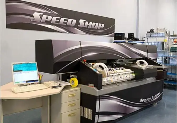
The Speed Shop rapid prototyping line builds qualification samples on the same equipment, with the same materials and operators that support production. That continuity allows the validated process window to transfer directly to volume manufacturing without separate requalification. Programs that prototype elsewhere often discover that prototype and production processes differ, which forces extra qualification cycles and delays release.
Full traceability runs from incoming material through final inspection. Every bond lot, equipment calibration record, operator qualification and test result is documented and retained in a controlled quality management system. When a customer program office or audit team requests records, the package arrives complete and retrievable.
Arrange a technical review to map wire bonding validation with Pro-Active Engineering’s team.
Frequently Asked Questions
What is the difference between MIL-STD-883 Method 2011 and Method 2023 and when are both required?
Method 2011, the pull test described earlier, evaluates the wire and both bond interfaces together. Method 2023, the shear test, isolates the ball-to-pad bond. High-reliability aerospace, defense and medical programs typically require both because they probe different failure mechanisms. A complete qualification package includes both test reports with full force distributions and failure mode classifications for every sample group.
What does BAMFIT testing add beyond the standard MIL-STD-883 reliability sequence?
The standard MIL-STD-883 reliability sequence covers temperature cycling, high-temperature storage, humidity and mechanical shock. BAMFIT, or Bond Assembly and Mechanical Fatigue Integrity Testing, adds combined mechanical fatigue loading that simulates cumulative vibration and stress over service life. Shock testing applies a single high-amplitude event. BAMFIT applies repeated lower-amplitude cycles that can expose fatigue-driven degradation at the bond interface that shock testing alone may miss. Post-BAMFIT pull and shear testing with retention criteria confirms that the bonded interface maintains margin after cumulative fatigue. Programs with extended service life or high-vibration environments gain value from including BAMFIT.
How does wire bonding process validation differ between aerospace or defense and medical device programs?
Both sectors require documented evidence that the process stays repeatable and controlled, but the governing frameworks differ. Aerospace and defense programs follow MIL-STD-883 for test methods, Nadcap for special process accreditation and AS9100 for quality management. Traceability requirements flow from prime contractor specifications and ITAR controls where applicable. Medical device programs follow FDA process validation guidance and ISO 13485, with validation structured as installation, operational and performance qualification phases. Documentation integrates into the design history file and links to the risk management file per ISO 14971. Change control in medical programs is strict, and any process parameter change outside the validated window typically triggers revalidation before production resumes. Aerospace and defense programs maintain similar change control expectations under AS9100 and Nadcap, but documentation structure and regulatory authority differ.
What traceability records does a Nadcap-compliant wire bonding validation package require?
A Nadcap-compliant package includes personnel qualification records for all operators and inspectors performing the special process, equipment calibration logs with current calibration traceable to national standards and process records that show scheduled parameters matched actual execution for every build. Lot traceability records link raw material lots through the special process to finished assemblies. Certificates of conformance include supplier identity, part number and revision, lot number, applicable specification reference, statement of conformance, authorized signature and date. For ITAR-controlled articles, the certificate also includes the applicable export-control statement. Pro-Active Engineering maintains these records within a controlled quality management system and can produce them for customer audits or program reviews.
How does Pro-Active Engineering’s Speed Shop reduce qualification risk during prototype builds?
The Speed Shop builds prototype assemblies on the same production equipment, with the same materials and operators that support the validated production process. This approach matters because process equivalence between prototype and production is a prerequisite for transferring a validated process window without extra qualification cycles. When prototypes run on a separate line or at a different supplier, the processes may not match and qualification data from prototypes may not apply to production. By running prototypes on production processes from the start, Pro-Active Engineering generates qualification data that supports the production release decision and shortens the path from validated process to scalable manufacturing.
Conclusion: From Prototype Bonds to Production-Ready Interconnects
Wire bonding process validation forms the documented bridge between a prototype bond and a production-ready, compliant interconnect process. The complete sequence of process-window characterization, DOE planning, MIL-STD-883 pull and shear testing, reliability and BAMFIT sequences, automated inspection, statistical reporting and sector-specific documentation builds the evidence base that aerospace, defense and medical programs require before production release.
Pro-Active Engineering delivers this sequence under one Nadcap-accredited, ITAR-registered roof with DFM integration from day one and Speed Shop prototypes built on production processes. The result is a traceable, transferable qualification package that supports scalable manufacturing without late-stage surprises.